
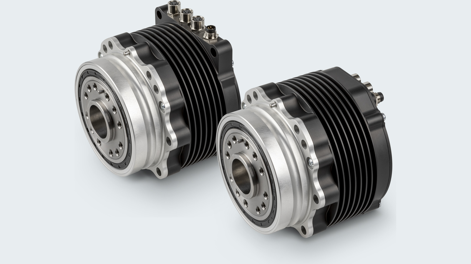
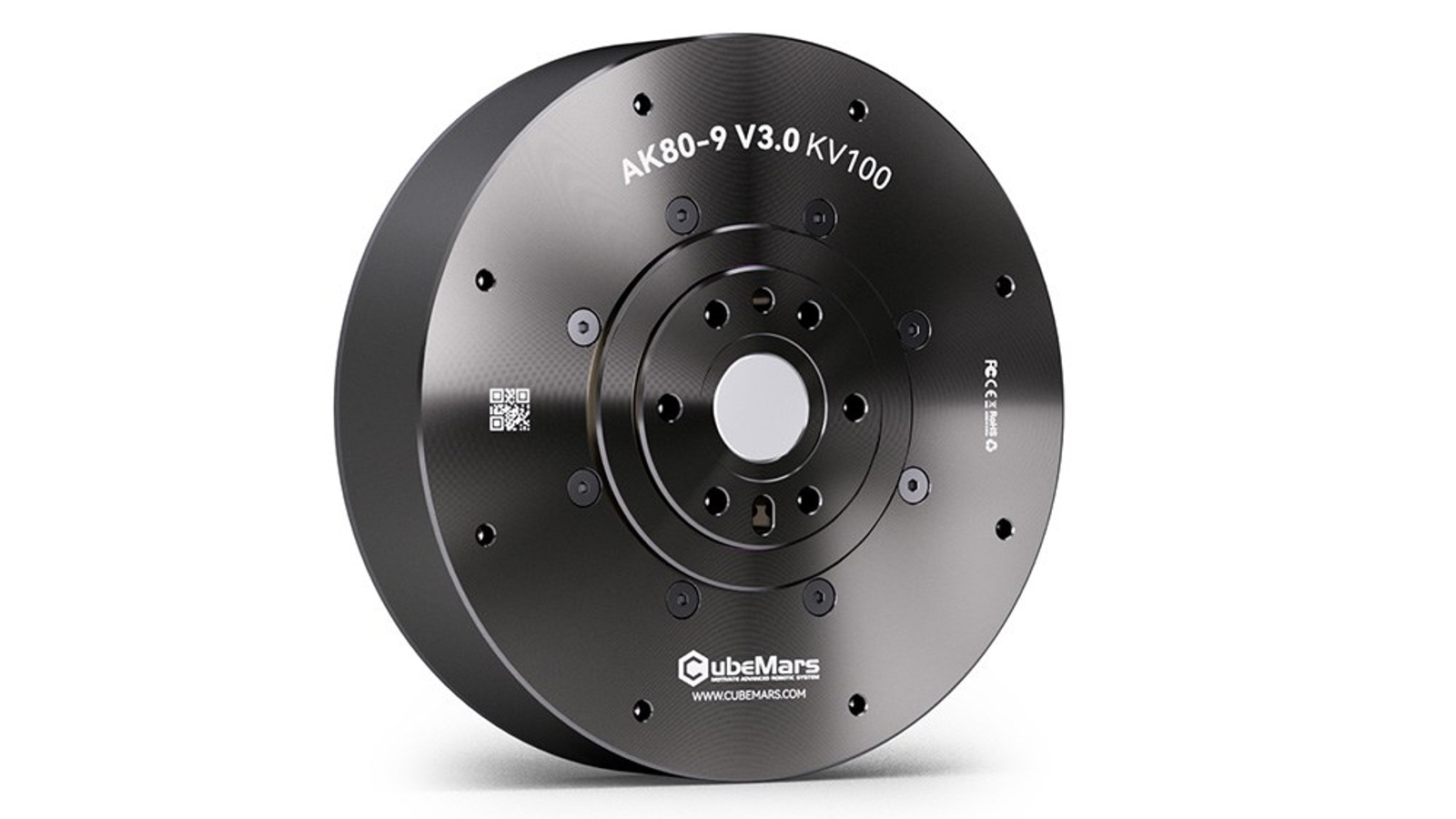
Integrated actuators
Motor, transmission and feedback packaged into a joint that moves and supports the robot.
Inside a rotary actuator
SpryDrive 8318: inspect a real motor, planetary transmission, output bearing and encoder assembly.
Drag to rotate · scroll to zoom
Loading CAD model…
SpryDrive 8318
Select a part to inspect its role.
7 motor turns = 1 output turn.
Source & model scope
Benjamin Bokser’s SpryDrive 8318 STEP assembly. Original part placements are preserved; the separate fasteners are hidden to keep the main assemblies clear. The section view clips the display to expose internals. This is one open actuator design, not the internal design of other products on this page. Movement follows the source’s 7:1 fixed-ring planetary arrangement. The input gear rotates seven times per output turn. Bearing rolling contact, motor electromagnetic forces, loads and efficiency are not simulated.
Original design · MIT licence · Conversion notes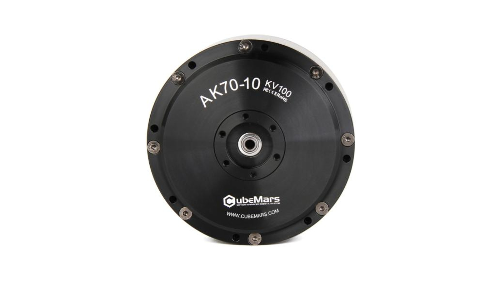
Architecture, materials & specificationsArchitecture options, material requirements and integration constraints
Architecture options
Quasi-direct drive combines a high-torque motor with low reduction. Gearbox type and reduction ratio are separate choices.
| Approach | Mechanism | Advantages | Trade-offs |
|---|---|---|---|
| High-ratio geared | A faster motor drives a large speed reduction. For the same motor, its inertia felt at the joint grows with the square of the ratio. | Reduces the motor torque needed for a given joint load. | Reducer stiffness, friction and load limits shape output performance. Holding a load with power off may require a brake. |
| Quasi-direct drive | A higher-torque motor uses a low reduction ratio. | Can reduce resistance to externally imposed motion, supporting responsive contact control. | Less torque multiplication requires more motor torque. Motor size, drive current and cooling are closely coupled. Impact durability depends on the complete joint. |
| Screw-driven linear | A screw produces extension; a linkage turns it into joint rotation. | Allows force-producing hardware to sit along the limb. | Changing leverage changes joint torque and speed through the stroke. Screw supports, side-load guidance and lubrication add integration requirements. |
Specifications & operating limits
Continuous output torque is tied to speed and cooling conditions; peak torque describes a limited duration with a recovery interval. Torque-to-mass comparisons depend on which components are included in the mass. Backlash is clearance on reversal; stiffness describes deflection under load. Backdrivability describes how easily external force moves the joint. Positioning accuracy and impact life depend on the assembled joint.
Materials & constraints
- Copper, magnetic steel & magnets
- A typical permanent-magnet motor combines current-carrying windings, a magnetic circuit and rotor magnets. Continuous output depends on getting heat out; the magnet, insulation and electronics each have their own temperature limits.
- Hardened gears & bearing steels
- Contact surfaces carry concentrated loads. Hardness resists wear, while toughness and fatigue strength help withstand repeated loading. Heat treatment, tooth geometry and lubrication affect wear and fatigue.
- Load-bearing housings
- The joint body holds the motor, gears and bearings in alignment while transferring loads into the limb. Aluminium offers low mass and useful heat conduction; steel offers greater stiffness for the same geometry, at greater mass. Ribs, wall thickness and bearing-seat geometry determine how much the finished housing flexes.
- Thermal contact & mounting
- Heat passes from the stator through its mounting interface and housing to the surroundings. Gaps and poorly conducting bonds restrict this path; bearings, lubricant and electronics have separate temperature limits.
Dependencies & engineering limits
- Work cycle & heat
- An actively held load can draw motor current even at zero speed. The resulting heat limits how long a joint can hold or repeat a movement. Continuous capability depends on the motion cycle, rest periods, heat path and drive-current limit. Frameless motors
- Manufacturing & assembly
- Gear geometry, bearing fits and housing alignment determine how the assembled joint carries load. Assembly also requires feedback setup and checks through the motion range. Buying the motor and reducer therefore leaves precision assembly and verification work; integration transfers some of that work to the module supplier. Bearings
- Drive electronics & interfaces
- Integrated drivers combine power transistors, gate drive and current sensing to save board space. Separate transistors allow different current and thermal requirements. Bus voltage, feedback interfaces and sustained current capability determine which motor and controller combinations work together. Compute & control
- Harness motion & service
- Bending and twisting stress cables differently. Cable construction, bend radius and connector access constrain the route through the joint. Strain relief keeps that motion from pulling on terminations; its placement must still allow the cable to twist and bend through the full travel. Structure & materials
Manufacturing & assembly
Parts & processes
No matching parts or examples.
Representative industrial route. Materials become motor parts, gearing and support hardware on separate production lines. These meet at joint assembly. This flow follows a permanent-magnet, strain-wave rotary actuator.
Rotor
Stator
Transmission
Housing
Control
Other routes
Manufacturing · Representative route. A sintered NdFeB, permanent-magnet motor route.
Related parts & processes 8
Manufacturing · Representative route. Magnetic core production and conductor winding meet in the motor.
Related parts & processes 5
Manufacturing · Representative route. Machined elements become a matched reduction stage for a rotary joint.
Related parts & processes 4
Manufacturing · Representative route. A roller-screw route from thread finishing to linear-actuator assembly.
Related parts & processes 6
Manufacturing · Representative route. A gear-cutting route leading into the planetary assembly, with planet gears, ring and carrier as supporting parts.
Related parts & processes 4
Integration / calibration · Representative route. Rotor and stator integrate with the housing, bearings and drive.
Related parts & processes 5
Manufacturing · Representative route. A primary rare-earth route; each stage needs its own industrial capability.
Manufacturing · Representative route. Coating and magnetisation are separate dependencies; the assembly determines their sequence.
Related parts & processes 3
Manufacturing · Representative route. A wire-production route feeding stator assembly alongside the laminated core.
Related parts & processes 2
Manufacturing · Equipment-maker example · EMAG. An equipment-maker process example for the nut; the shaft and rollers have separate production routes.
Related parts & processes 1
Assembly · Representative route. Nabtesco’s documented architecture, with separate crankshaft and pin-and-gear dependencies.
Related parts & processes 1
Assembly · Representative route. A geared rotary joint: motor, one reduction stage, bearings and feedback meet at assembly, followed by wiring and drive commissioning.
Related parts & processes 9
Manufacturing · Company-disclosed process · Laifual. The manufacturer’s disclosed route, from outsourced blanks to in-house finishing and assembly.
Related parts & processes 4
Manufacturing · Company-disclosed process · Seenpin. Shaft, rollers and nut follow parallel routes. Standard parts join them at assembly.
Related parts & processes 2
Manufacturing · Company-disclosed process · Seenpin. Shaft, rollers and nut follow parallel routes. Standard parts join them at assembly.
Related parts & processes 2
Manufacturing · Company-disclosed process · Seenpin. Shaft, rollers and nut follow parallel routes. Standard parts join them at assembly.
Related parts & processes 2
Assembly · Company-disclosed process · Direct Drive. A disclosed factory assembly sequence. PCB surface mounting is among the supplementary processes contracted out.
Related parts & processes 4
Assembly · Representative route. Cable preparation, termination and electrical testing feed the motor’s power and feedback connections.
Related parts & processes 5
Assembly · Representative route. A bonded permanent-magnet rotor; stator manufacture runs in parallel.
Related parts & processes 2
Manufacturing · Representative route. The housing is made separately from the motor and bought-in bearings.
Related parts & processes 1
Assembly · Representative route. Board assembly supplies the drive; encoder and harness join when the joint is wired.
Related parts & processes 2
Assembly · Representative route. Separate inputs converge into the supplied component.
Related parts & processes 7
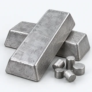
Alloy composition sets the balance between magnetic strength and temperature capability.
Material input to NdFeB alloy: Metals & alloy feed.
Material input to Alloy casting & powder preparation: NdFeB alloy.
NdFeB alloy
Neodymium, iron and boron form the magnetic alloy in this sintered-magnet route. Grade selection trades magnetic performance against temperature requirements.
Heavy-rare-earth additions vary by grade.
Inputs & supporting parts
Refined oxides are converted into metals that feed magnet alloy production.
Where this fits
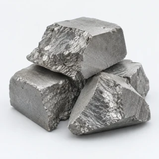
Cast alloy becomes powder through crushing and milling.
Sources & technical scope
Illustrative images of generic materials and components.
This step
Related references
Powder alignment, pressing and sintering form a magnet body with the required geometry and magnetic properties.
Sequence: Powder alignment & pressing → Pressing & sintering.
Sequence: Alloy casting & powder preparation → Pressing & sintering.
Production step for Permanent magnets: Pressing & sintering.
Sequence: Pressing & sintering → Magnet grinding & sizing.
94% China share · Global sintered permanent-magnet production · 2024
Across industries; not a robotics-specific share. Mining and refining are separate supply stages.
Pressing & sintering
Powder processing, alignment, pressing and sintering create the magnet material. Pressing route and alloy composition affect its magnetic properties.
Inputs & supporting parts
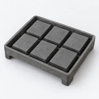
A magnetic field aligns powder particles; pressure compacts the powder into a body for sintering.
Cast alloy becomes powder through crushing and milling.
Where this fits
Provide the rotor field; grade and geometry must suit the motor.
After sintering and heat treatment, abrasive grinding or slicing brings the hard, brittle magnet body to its finished dimensions.
Sources & technical scope
Illustrative images of generic materials and components.
Related references
Permanent magnets provide the rotor field. Their grade, shape and retention are selected for the motor’s temperature and speed.
Production step for Permanent magnets: Pressing & sintering.
Possible production process for Permanent magnets: Grain-boundary diffusion.
Production step for Permanent magnets: Protective magnet coating.
Supporting dependency for Permanent magnets: Magnetisation & pole pattern.
Used in Frameless motor: Permanent magnets.
Used in Rotor mounting & air gap: Permanent magnets.
Assembly input to Rotor magnet bonding: Permanent magnets.
94% China share · Global sintered permanent-magnet production · 2024
Across industries; not a robotics-specific share. Mining and refining are separate supply stages.
This step
Related references
US DOE - magnet production stages (2022 technical reference, section 2.2)Kollmorgen · TBM2GTDK - HAL grain-boundary diffusionYunsheng · application proof, pp. 131–132Kollmorgen - frameless rotor/stator installationArnold · NdFeB grades and protective coatingsArnold · magnetisation and fixturesDirect Drive Tech · prospectus, pp. 163–164
Industrial significance
Permanent magnets
Frameless motors →Finished magnets provide the rotor magnetic field in this permanent-magnet motor architecture. Their dimensions, grade and retention must suit the motor.
Inputs & supporting parts
Aligns and consolidates alloy powder into the magnet material.
A dysprosium- or terbium-bearing layer is applied to the magnet and diffused by heat treatment.
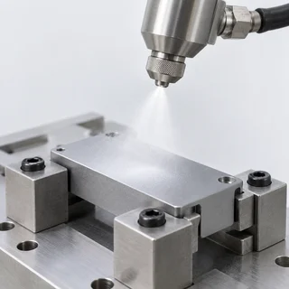
A suitable coating protects corrosion-sensitive NdFeB material.
An applied field magnetises the material in the required direction or pole pattern.
Where this fits
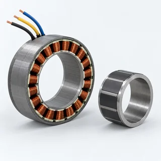
Rotor and stator supply torque within the joint; bearings, feedback and cooling complete the installation.
Locates the rotor relative to the stator and sets clearance between their magnetic surfaces.
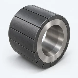
Bonds the shaft, magnetic yoke and magnets into a rotor assembly.
Examples from industry 1
 Generic
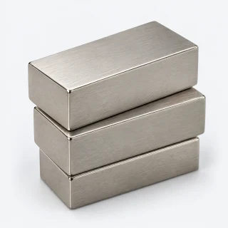
Sintered NdFeB magnets add alloy preparation, powder processing, pressing and sintering to the motor supply chain. Temperature capability and heavy-rare-earth content vary by grade.
Sources & technical scope
Illustrative images of generic materials and components.
This step
Related references
US DOE - magnet production stages (2022 technical reference, section 2.2)Kollmorgen · TBM2GTDK - HAL grain-boundary diffusionYunsheng · application proof, pp. 131–132Kollmorgen - frameless rotor/stator installationArnold · NdFeB grades and protective coatingsArnold · magnetisation and fixturesDirect Drive Tech · prospectus, pp. 163–164
The joint housing locates the frameless rotor and stator and provides bearing support, cooling and feedback.
Used in Frameless motor: Permanent magnets.
Production step for Frameless motor: Winding & assembly.
Supporting dependency for Frameless motor: Servo electronics.
Assembly input to Frameless motor: Assembled rotor.
Assembly input to Frameless motor: Wound & checked stator.
Used in Rotary joint: Frameless motor.
Assembly input to Stator mounting & heat path: Frameless motor.
Assembly input to Integrated rotary actuator: Frameless motor.
Frameless motor
Frameless motors →Rotor and stator are integrated into the joint structure. Bearings, sensing, drive electronics and thermal management complete the installation.
Continuous torque depends on cooling and operating conditions.
Inputs & supporting parts
Provide the rotor field; grade and geometry must suit the motor.
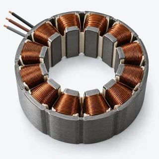
Forms insulated conductors into stator coils.
The drive supplies controlled motor current and closes feedback loops.
The magnetic yoke, shaft and bonded magnets form the rotor.
The laminated core and insulated coils form the stator.
Where this fits
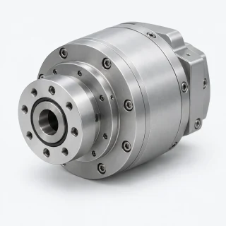
Combines motor, transmission and feedback to drive a robot joint.
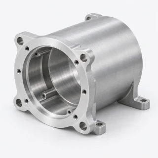
The wound stator is secured in a rigid housing that conducts heat away.
Motor, strain-wave reducer, bearings, housing, encoder and drive form this rotary-joint architecture.
Examples from industry 1
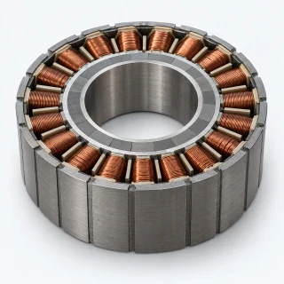 Generic
A frameless motor supplies the electromagnetics. The joint still needs a housing, bearing support, feedback and a thermal path. Continuous performance depends on the installed cooling and operating conditions.
Sources & technical scope
Illustrative images of generic materials and components.
This step
Related references
The motor generates rotation, the reducer increases output torque, and feedback lets the controller regulate joint movement.
Used in Rotary joint: Frameless motor.
Used in Rotary joint: Strain-wave reducer.
Supporting dependency for Rotary joint: Position feedback.
Supporting dependency for Rotary joint: Bearing support.
Optional component of Rotary joint: Holding brake.
Used in Rotary joint: Planetary reduction.
Production step for Rotary joint: Lead routing & grounding.
Design alternative for Rotary joint: RV reduction assembly.
Design alternative for Rotary joint: Strain-wave reducer.
Checks on Rotary joint: Alignment & electrical checks.
Sequence: Rotary joint → Alignment & electrical checks.
This step
Related references
Kollmorgen · TBM2GHarmonic Drive · component setsRLS · AksIM-2THK · cross-roller ringsmayr · ROBA-servostop CobotNeugart · planetary gearbox constructionKollmorgen - frameless rotor/stator installationNabtesco · RV construction and operating principleKollmorgen · TBM2G installation, grounding and alignment, sections 1.3.2–1.3.7
Rotary joint
A geared rotary actuator integrates motor, reduction and feedback; some products also integrate the servo drive. The magnet, stator and reducer routes converge here.
Inputs & supporting parts
Rotor and stator supply torque within the joint; bearings, feedback and cooling complete the installation.
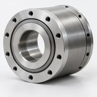
The assembled reduction stage trades motor speed for joint torque.
An encoder reports position to the controller.
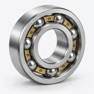
Bearings carry radial, axial and moment loads and locate the moving assembly.
A spring-applied brake can retain position when release power is removed.
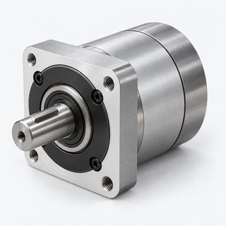
Sun, planet and internal ring gears transmit motion through a planet carrier.
Phase, temperature-sensor and feedback wiring connects the motor to its drive.
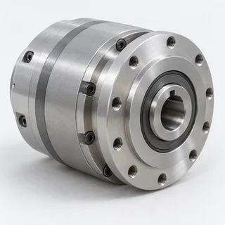
The spur and pin-and-gear stages combine to reduce speed and transmit output torque.
Where this fits

Rotor alignment establishes the motor air gap.
Sources & technical scope
Illustrative images of generic materials and components.
This step
Related references
Kollmorgen · TBM2GHarmonic Drive · component setsRLS · AksIM-2THK · cross-roller ringsmayr · ROBA-servostop CobotNeugart · planetary gearbox constructionKollmorgen - frameless rotor/stator installationNabtesco · RV construction and operating principleKollmorgen · TBM2G installation, grounding and alignment, sections 1.3.2–1.3.7
Electrical steel carries magnetic flux in the motor core. Grade and processing affect magnetic losses and mechanical properties.
Material input to Laminated core: Electrical steel.
This step
Electrical steel
Non-grain-oriented electrical steel supplies magnetic core material for motors. Magnetic losses and material homogeneity matter alongside mechanical properties.
Where this fits
Stacked electrical-steel sheets guide magnetic flux and limit eddy-current losses.
Examples from industry 1
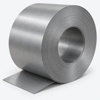 Generic
Non-grain-oriented electrical steel is an input to motor cores. Magnetic properties and losses guide grade selection. voestalpine offers grades for motor applications.
Sources & technical scope
Illustrative images of generic materials and components.
This step
Link to this detailElectrical-steel laminations are formed and stacked to create the motor core. Grade, geometry and processing affect magnetic performance.
Material input to Laminated core: Electrical steel.
Material input to Laminated core: Electrical-steel insulation.
Assembly input to Winding & assembly: Laminated core.
Laminated core
Electrical-steel laminations form the motor’s magnetic core. Material grade and processing affect magnetic performance.
Inputs & supporting parts
Non-grain-oriented electrical steel supplies magnetic core material for motors.
Insulation coatings separate adjacent electrical-steel laminations; bonding coatings can also help retain the stack.
Where this fits
Forms insulated conductors into stator coils.
Examples from industry 1
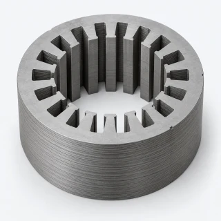 Generic
Godrej documents stamped laminations, stator stacks and rotor assemblies, including custom stack heights and slot geometries. This adds tooling and core assembly between electrical steel and a finished motor.
Sources & technical scope
Illustrative images of generic materials and components.
This step
Related references
Winding and insertion equipment forms and places coils in the stator. Tooling follows the slot geometry and assembly sequence.
Assembly input to Winding & assembly: Laminated core.
Production equipment for Winding & assembly: Winding equipment.
Material input to Winding & assembly: Insulated winding wire.
Production step for Frameless motor: Winding & assembly.
Assembly input to Stator mounting & heat path: Winding & assembly.
Checks on Winding & assembly: Stator electrical checks.
Winding & assembly
Equipment-maker reference · GROBConductors are formed into coils and assembled into the stator. Winding and insertion methods depend on the slots, coil geometry and assembly sequence.
The winding method and tooling must suit the stator geometry.
Inputs & supporting parts
Stacked electrical-steel sheets guide magnetic flux and limit eddy-current losses.
Winding machines form coils; insertion and assembly systems place them in the stator.
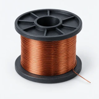
Carries current through the stator coils; insulation separates adjacent turns.
Where this fits
Rotor and stator supply torque within the joint; bearings, feedback and cooling complete the installation.
The wound stator is secured in a rigid housing that conducts heat away.
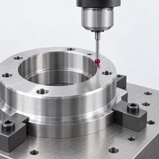
The stator is inspected, phase connections soldered, bearings press-fitted and the control board installed.
Examples from industry 1
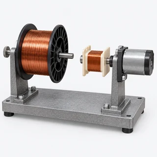 Generic
Needle, flyer and linear winding are different ways to form motor coils. Winding, insertion and assembly equipment must match the stator geometry.
Sources & technical scope
Illustrative images of generic materials and components.
Related references
Winding machines form coils; insertion and assembly systems place them in the stator.
Production equipment for Winding & assembly: Winding equipment.
Winding equipment
Equipment-maker reference · GROBWinding machines form coils; insertion and assembly systems place them in the stator.
Equipment for this step →Where this fits
Forms insulated conductors into stator coils.
Sources & technical scope
Illustrative images of generic materials and components.
Link to this detailGear teeth and locating surfaces require controlled geometry. Machining and inspection capabilities determine the fit of the mating parts.
Production equipment for Precision machining: Gear-cutting equipment.
Material input to Precision machining: Mechanical steel selection.
Production step for Gear elements: Precision machining.
This step
Precision machining
Equipment-maker reference · GleasonGear teeth and locating surfaces require controlled geometry. Machining and inspection capabilities determine the fit of the mating parts.
The gear design determines the machining and metrology requirements.
Inputs & supporting parts
Power skiving machines and tooling can produce internal and external gear teeth.
Gear components require a steel grade and heat treatment selected for their loads and manufacturing route.
Where this fits
A strain-wave set combines a flexspline, circular spline and wave generator.
Examples from industry 1
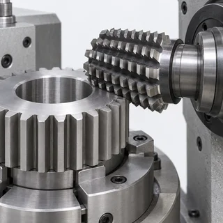 Generic
Power skiving is one route for machining internal and external gear teeth. Machine, tooling and process choice depend on the gear design.
Sources & technical scope
Illustrative images of generic materials and components.
This step
Link to this detailThe wave generator deforms the flexspline so its teeth engage the circular spline. These three parts form the reduction mechanism.
Production step for Gear elements: Precision machining.
Used in Gear elements: Flexspline.
Used in Gear elements: Circular spline.
Used in Gear elements: Wave generator.
Assembly input to Alignment & lubrication: Gear elements.
Checks on Gear elements: Gear inspection.
Gear elements
A strain-wave set combines a flexspline, circular spline and wave generator. The wave generator deforms the flexspline to engage the circular spline.
Inputs & supporting parts
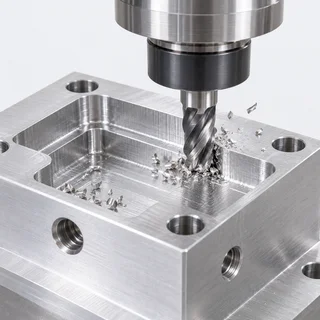
Gear teeth and locating surfaces require controlled geometry.
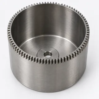
In a cup-type strain-wave set, the thin externally toothed flexspline flexes radially as the wave generator rotates.
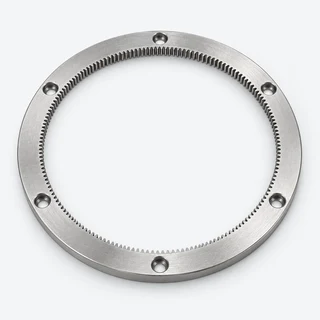
A rigid internally toothed ring engages the flexspline at two regions in the illustrated strain-wave arrangement.
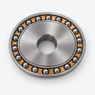
An elliptical hub and thin-race bearing deform the flexspline and drive the engagement pattern.
Where this fits
The gear elements must be installed concentrically and retained as their factory-matched set, with the specified lubricant and mounting tolerances.
Dimensional gear inspection and surface-roughness measurement check manufactured geometry.
Sources & technical scope
Illustrative images of generic materials and components.
This step
Related references
Concentric mounting, matched gear elements and specified lubrication control engagement, friction and wear.
Assembly input to Alignment & lubrication: Gear elements.
Production step for Strain-wave reducer: Alignment & lubrication.
Related references
Alignment & lubrication
The gear elements must be installed concentrically and retained as their factory-matched set, with the specified lubricant and mounting tolerances.
Mixing unmatched elements or misalignment can compromise performance and service life.
Inputs & supporting parts
A strain-wave set combines a flexspline, circular spline and wave generator.
Where this fits
The assembled reduction stage trades motor speed for joint torque.
Sources & technical scope
Illustrative images of generic materials and components.
Related references
The reduction stage trades motor speed for output torque. Its housing and bearings support the assembled gear set.
Production step for Strain-wave reducer: Alignment & lubrication.
Used in Rotary joint: Strain-wave reducer.
Design alternative for Rotary joint: Strain-wave reducer.
Assembly input to Integrated rotary actuator: Strain-wave reducer.
Strain-wave reducer
Strain-wave / harmonic reducers →The assembled reduction stage trades motor speed for joint torque. A component set still needs the specified housing and load support.
Inputs & supporting parts
The gear elements must be installed concentrically and retained as their factory-matched set, with the specified lubricant and mounting tolerances.
Where this fits
Combines motor, transmission and feedback to drive a robot joint.
Motor, strain-wave reducer, bearings, housing, encoder and drive form this rotary-joint architecture.
Examples from industry 1
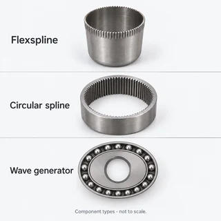 Generic
The wave generator, flexible spline and circular spline form a matched reduction stage. Component sets and housed gear units differ in their bearing support and integration requirements.
Sources & technical scope
Illustrative images of generic materials and components.
This step
Related references
Power skiving machines and tooling can produce internal and external gear teeth. Process selection depends on tooth geometry and tool access.
Production equipment for Precision machining: Gear-cutting equipment.
This step
Gear-cutting equipment
Equipment-maker reference · GleasonPower skiving machines and tooling can produce internal and external gear teeth. Process selection depends on tooth geometry and tool access.
Equipment for this step →Where this fits
Gear teeth and locating surfaces require controlled geometry.
Sources & technical scope
Illustrative images of generic materials and components.
This step
Link to this detailThread grinding controls the contact geometry that lets the screw, nut and rollers transfer load.
Production equipment for Thread grinding: Thread grinder.
Production step for Screw, nut & rollers: Thread grinding.
Related references
Thread grinding
Equipment-maker reference · EMAGGrinding finishes the thread profile and contact surfaces after earlier machining. Accurate lead and form allow the screw, nut and rollers to share load.
The finishing route depends on part geometry and hardness. Tool access, workholding and inspection affect repeatability.
Inputs & supporting parts
Thread grinders finish precision threaded surfaces.
Where this fits
Threaded screw, nut and rollers provide the rolling contacts that convert motor rotation into linear motion.
Examples from industry 1
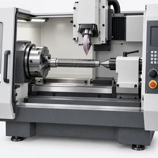 Generic
Thread grinding finishes the contact geometry after earlier machining. Tool access, workholding and part hardness affect the process.
Sources & technical scope
Illustrative images of generic materials and components.
Related references
Threaded rollers transfer load between the screw and nut as rotation produces linear travel.
Production step for Screw, nut & rollers: Thread grinding.
Used in Screw, nut & rollers: Threaded screw shaft.
Used in Screw, nut & rollers: Threaded rollers.
Used in Screw, nut & rollers: Roller-screw nut.
Assembly input to Roller-screw assembly: Screw, nut & rollers.
This step
Related references
Screw, nut & rollers
Threaded screw, nut and rollers provide the rolling contacts that convert motor rotation into linear motion.
Inputs & supporting parts
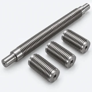
Grinding finishes the thread profile and contact surfaces after earlier machining.
The screw’s thread engages the threaded rollers in a planetary roller screw.
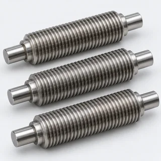
Multiple threaded rollers transfer load between the screw and nut.
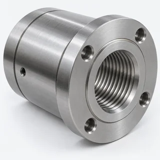
The nut surrounds the threaded roller arrangement and transfers axial load.
Where this fits
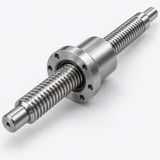
The assembled screw drive produces linear travel and force.
Sources & technical scope
Illustrative images of generic materials and components.
This step
Related references
The screw transmission converts rotation into linear travel. Lead, preload and load history affect force and motion.
Assembly input to Roller-screw assembly: Screw, nut & rollers.
Assembly input to Roller-screw assembly: Threaded screw shaft.
Assembly input to Roller-screw assembly: Threaded rollers.
Assembly input to Roller-screw assembly: Roller-screw nut.
Assembly input to Drive & support assembly: Roller-screw assembly.
Checks on Roller-screw assembly: Screw assembly testing.
Checks on Roller-screw assembly: Lead accuracy & backlash acceptance.
Roller-screw assembly
Roller screws & linear actuation →The assembled screw drive produces linear travel and force. Lead, speed, preload and load history influence selection and operation.
Inputs & supporting parts
Threaded screw, nut and rollers provide the rolling contacts that convert motor rotation into linear motion.
The screw’s thread engages the threaded rollers in a planetary roller screw.
Multiple threaded rollers transfer load between the screw and nut.
The nut surrounds the threaded roller arrangement and transfers axial load.
Where this fits
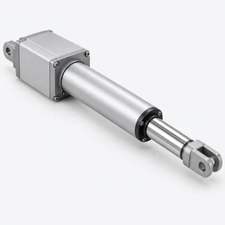
Motor drive, support bearings, guidance and mounting integrate the screw transmission into a linear actuator.
After assembly adjustment and grease filling, Seenpin tests the completed screw before warehousing.
Tolomatic’s catalogue specifies lead accuracy of 0.023 mm per 300 mm and backlash of 0.03 mm for its listed screws.
Examples from industry 1
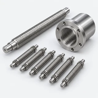 Generic
A roller screw converts rotation into linear motion through precision-ground threaded parts. It is an input to a linear actuator; motor, support bearings, guidance and sensing are additional integration choices.
Sources & technical scope
Illustrative images of generic materials and components.
This step
Related references
A motor drives the screw transmission; bearings, guidance and mounts support its loads and movement.
Assembly input to Drive & support assembly: Roller-screw assembly.
Supporting dependency for Drive & support assembly: Bearing support.
Supporting dependency for Drive & support assembly: Servo electronics.
Supporting dependency for Drive & support assembly: Position feedback.
Production step for Linear actuator: Drive & support assembly.
Drive & support assembly
Motor drive, support bearings, guidance and mounting integrate the screw transmission into a linear actuator.
Inputs & supporting parts
The assembled screw drive produces linear travel and force.
Bearings carry radial, axial and moment loads and locate the moving assembly.
The drive supplies controlled motor current and closes feedback loops.
An encoder reports position to the controller.
Where this fits
In this route, a motor drives a roller screw to deliver linear travel and force to the connected mechanism.
Sources & technical scope
Illustrative images of generic materials and components.
This step
Related references
The actuator delivers linear movement to the connected mechanism. Stroke, force and mounting geometry determine its integration.
Production step for Linear actuator: Drive & support assembly.
Linear actuator
Roller screws & linear actuation →In this route, a motor drives a roller screw to deliver linear travel and force to the connected mechanism.
Inputs & supporting parts
Motor drive, support bearings, guidance and mounting integrate the screw transmission into a linear actuator.
Sources & technical scope
Illustrative images of generic materials and components.
This step
Link to this detailThread grinders finish precision threaded surfaces. Tooling and process setup control thread geometry and surface condition.
Production equipment for Thread grinding: Thread grinder.
Thread grinder
Equipment-maker reference · EMAGThread grinders finish precision threaded surfaces. Tooling and process setup control thread geometry and surface condition.
Equipment for this step →Where this fits
Grinding finishes the thread profile and contact surfaces after earlier machining.
Sources & technical scope
Illustrative images of generic materials and components.
Link to this detailAn encoder reports position to the controller. Motor-side and output-side feedback observe different points in the transmission.
Supporting dependency for Rotary joint: Position feedback.
Supporting dependency for Drive & support assembly: Position feedback.
Supporting dependency for Lead routing & grounding: Position feedback.
Supporting dependency for Drive setup & motion checks: Position feedback.
Assembly input to Integrated rotary actuator: Position feedback.
Position feedback
Encoders & position sensors →An encoder reports position to the controller. Motor-side and output-side feedback observe different points in the transmission.
Installed accuracy depends on mounting error and mechanical deflection.
Where this fits
Combines motor, transmission and feedback to drive a robot joint.
Motor drive, support bearings, guidance and mounting integrate the screw transmission into a linear actuator.
Phase, temperature-sensor and feedback wiring connects the motor to its drive.

Motor parameters and feedback settings configure the drive.
Motor, strain-wave reducer, bearings, housing, encoder and drive form this rotary-joint architecture.
Examples from industry 1
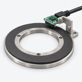 Generic
The magnetic ring and readhead need the specified mounting geometry and a compatible electrical interface. Encoder resolution, installed accuracy and motor-side versus output-side measurement describe different properties.
Sources & technical scope
Illustrative images of generic materials and components.
This step
Related references
Bearings carry radial, axial and moment loads and locate the moving assembly. The specific bearing arrangement follows the joint geometry and load case.
Supporting dependency for Rotary joint: Bearing support.
Supporting dependency for Drive & support assembly: Bearing support.
Supporting dependency for Rotor mounting & air gap: Bearing support.
Assembly input to Rotor mounting & air gap: Bearing support.
Assembly input to Integrated rotary actuator: Bearing support.
Bearing support
Bearings →Bearings carry radial, axial and moment loads and locate the moving assembly. The specific bearing arrangement follows the joint geometry and load case.
Where this fits
Combines motor, transmission and feedback to drive a robot joint.
Motor drive, support bearings, guidance and mounting integrate the screw transmission into a linear actuator.
Locates the rotor relative to the stator and sets clearance between their magnetic surfaces.
Motor, strain-wave reducer, bearings, housing, encoder and drive form this rotary-joint architecture.
Examples from industry 1
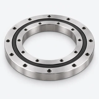 Generic
Crossed rollers can carry radial, axial and moment loads in a compact joint. Select the bearing and mounting for the radial, axial and moment loads at the output.
Sources & technical scope
Illustrative images of generic materials and components.
This step
Related references
The drive supplies controlled motor current and closes feedback loops. Power, sensing and communications interfaces must match the motor and controller.
Sequence: Drive-board assembly → Servo electronics.
Supporting dependency for Frameless motor: Servo electronics.
Supporting dependency for Drive & support assembly: Servo electronics.
Supporting dependency for Lead routing & grounding: Servo electronics.
Supporting dependency for Drive setup & motion checks: Servo electronics.
Assembly input to Integrated rotary actuator: Servo electronics.
This step
Related references
Kollmorgen · TBM2GSchaeffler · screw support, preload and working-cycle checksSchaeffler · modular Ewellix linear actuatorsKollmorgen - frameless rotor/stator installationKollmorgen · motor parameters, feedback and phase checksEurocircuits · assembly data, placement and solderingHarmonic Drive · integrated actuator
Servo electronics
Compute & control →The drive supplies controlled motor current and closes feedback loops. Power, sensing and communications interfaces must match the motor and controller.
Inputs & supporting parts
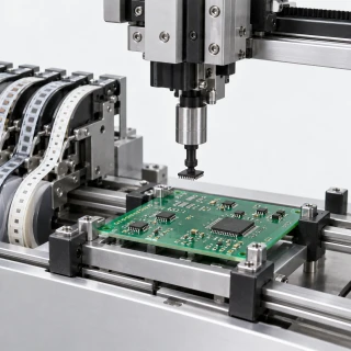
Bare boards, power switches, control ICs and connectors become the drive through component placement, soldering and inspection.
Where this fits
Rotor and stator supply torque within the joint; bearings, feedback and cooling complete the installation.
Motor drive, support bearings, guidance and mounting integrate the screw transmission into a linear actuator.
Phase, temperature-sensor and feedback wiring connects the motor to its drive.
Motor parameters and feedback settings configure the drive.
Motor, strain-wave reducer, bearings, housing, encoder and drive form this rotary-joint architecture.
Examples from industry 1
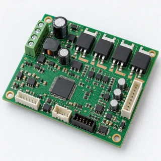 Generic
A compact servo drive closes motor-control loops and supplies motor current. Voltage, current, feedback and communication interfaces must fit the joint. This layer serves a different function from perception or planning compute.
Sources & technical scope
Illustrative images of generic materials and components.
This step
Related references
Kollmorgen · TBM2GSchaeffler · screw support, preload and working-cycle checksSchaeffler · modular Ewellix linear actuatorsKollmorgen - frameless rotor/stator installationKollmorgen · motor parameters, feedback and phase checksEurocircuits · assembly data, placement and solderingHarmonic Drive · integrated actuator
A spring-applied brake can retain position when release power is removed. Whether it is required and how it is sized depend on the joint and safety design.
Optional component of Rotary joint: Holding brake.
This step
Related references
Holding brake
A spring-applied brake can retain position when release power is removed. Whether it is required and how it is sized depend on the joint and safety design.
Where this fits
Combines motor, transmission and feedback to drive a robot joint.
Examples from industry 1
 Generic
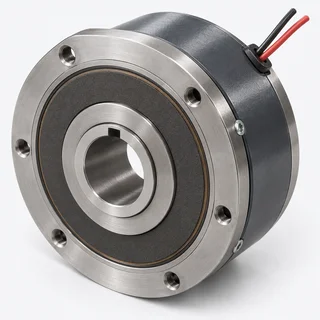
A spring-applied brake can hold a joint when electrical release power is removed. Hollow-shaft robot designs impose space and torque constraints. Brake selection depends on the joint’s holding requirements.
Sources & technical scope
Illustrative images of generic materials and components.
This step
Related references
Separation turns mixed rare-earth feeds into individual oxides.
Sequence: Chemical upgrading → Rare-earth separation.
Production step for Metals & alloy feed: Rare-earth separation.
Rare-earth separation
Separation turns mixed rare-earth feeds into individual oxides.
Inputs & supporting parts
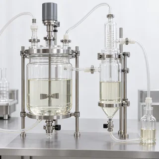
Chemical processing prepares mixed rare-earth feed for separation into individual oxides.
Where this fits
Refined oxides are converted into metals that feed magnet alloy production.
Sources & technical scope
Illustrative images of generic materials and components.
Link to this detailRefined oxides are converted into metals that feed magnet alloy production.
Production step for Metals & alloy feed: Rare-earth separation.
Material input to NdFeB alloy: Metals & alloy feed.
Related references
Metals & alloy feed
Refined oxides are converted into metals that feed magnet alloy production.
Inputs & supporting parts
Separation turns mixed rare-earth feeds into individual oxides.
Where this fits
Neodymium, iron and boron form the magnetic alloy in this sintered-magnet route.
Sources & technical scope
Illustrative images of generic materials and components.
Related references
A magnetic field aligns powder particles; pressure compacts the powder into a body for sintering.
Sequence: Powder alignment & pressing → Pressing & sintering.
Powder alignment & pressing
A magnetic field aligns powder particles; pressure compacts the powder into a body for sintering.
VAC describes alternative isostatic and die-pressing routes; geometry and grade determine the choice.
Where this fits
Aligns and consolidates alloy powder into the magnet material.
Sources & technical scope
Illustrative images of generic materials and components.
Link to this detailA dysprosium- or terbium-bearing layer is applied to the magnet and diffused by heat treatment. Concentrating these elements at grain boundaries raises resistance to demagnetisation with less heavy rare earth.
Possible production process for Permanent magnets: Grain-boundary diffusion.
Related references
Grain-boundary diffusion
Includes company disclosure · YunshengA dysprosium- or terbium-bearing layer is applied to the magnet and diffused by heat treatment. Concentrating these elements at grain boundaries raises resistance to demagnetisation with less heavy rare earth.
Yunsheng lists diffusion after magnet machining as an optional, grade-dependent step.
Where this fits
Provide the rotor field; grade and geometry must suit the motor.
Sources & technical scope
Illustrative images of generic materials and components.
Related references
In a cup-type strain-wave set, the thin externally toothed flexspline flexes radially as the wave generator rotates.
Used in Gear elements: Flexspline.
Related references
Flexspline
In a cup-type strain-wave set, the thin externally toothed flexspline flexes radially as the wave generator rotates.
Cup, hat and other forms are product-specific; use the specified matched component set.
Where this fits
A strain-wave set combines a flexspline, circular spline and wave generator.
Sources & technical scope
Illustrative images of generic materials and components.
Related references
A rigid internally toothed ring engages the flexspline at two regions in the illustrated strain-wave arrangement.
Used in Gear elements: Circular spline.
Related references
Circular spline
A rigid internally toothed ring engages the flexspline at two regions in the illustrated strain-wave arrangement.
Tooth geometry and the matched component set determine engagement.
Where this fits
A strain-wave set combines a flexspline, circular spline and wave generator.
Sources & technical scope
Illustrative images of generic materials and components.
Related references
An elliptical hub and thin-race bearing deform the flexspline and drive the engagement pattern.
Used in Gear elements: Wave generator.
Related references
Wave generator
An elliptical hub and thin-race bearing deform the flexspline and drive the engagement pattern.
Where this fits
A strain-wave set combines a flexspline, circular spline and wave generator.
Sources & technical scope
Illustrative images of generic materials and components.
Related references
Gear metrology checks tooth geometry and surface condition against the assembly requirements.
Checks on Gear elements: Gear inspection.
Checks on Sun gear: Gear inspection.
Checks on Planet gears: Gear inspection.
Checks on Internal ring gear: Gear inspection.
Related references
Gear inspection
Equipment-maker reference · GleasonDimensional gear inspection and surface-roughness measurement check manufactured geometry.
Workpiece geometry and tolerances determine the measurement setup.
Production & inspection
Gleason’s 175GMS nano combines gear metrology with scanning probes and surface measurement; equipment and setup must fit the workpiece.
Inputs & supporting parts
A strain-wave set combines a flexspline, circular spline and wave generator.
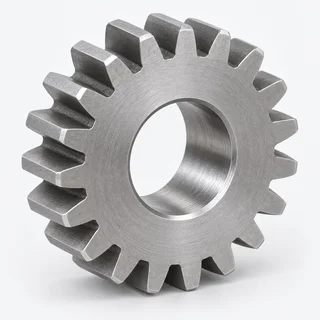
The central gear engages the surrounding planet gears.
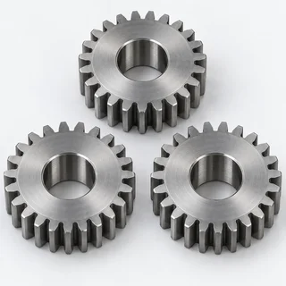
The planet gears mesh with both the sun and internal ring.
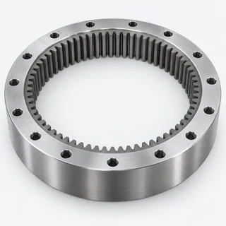
An outer gear carries internal teeth around the planets.
Sources & technical scope
Illustrative images of generic materials and components.
Related references
Sun, planet and internal ring gears transmit motion through a planet carrier.
Used in Planetary reduction: Sun gear.
Used in Planetary reduction: Planet gears.
Used in Planetary reduction: Internal ring gear.
Used in Planetary reduction: Planet carrier.
Used in Rotary joint: Planetary reduction.
Related references
Planetary reduction
Sun, planet and internal ring gears transmit motion through a planet carrier.
This is an alternative reduction architecture to the strain-wave route.
Inputs & supporting parts
The central gear engages the surrounding planet gears.
The planet gears mesh with both the sun and internal ring.
An outer gear carries internal teeth around the planets.
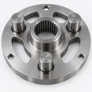
The carrier supports the planet gears and connects them to the output.
Where this fits
Combines motor, transmission and feedback to drive a robot joint.
Sources & technical scope
Illustrative images of generic materials and components.
Related references
The central gear engages the surrounding planet gears.
Possible production process for Sun gear: Gear-tooth cutting.
Used in Planetary reduction: Sun gear.
Checks on Sun gear: Gear inspection.
Sun gear
The central gear engages the surrounding planet gears.
The input/output arrangement must be specified for the complete stage.
Inputs & supporting parts
Hobbing and power skiving are available routes for small external gears; power skiving also serves internal gears.
Where this fits
Sun, planet and internal ring gears transmit motion through a planet carrier.
Dimensional gear inspection and surface-roughness measurement check manufactured geometry.
Sources & technical scope
Illustrative images of generic materials and components.
Link to this detailThe planet gears mesh with both the sun and internal ring.
Possible production process for Planet gears: Gear-tooth cutting.
Used in Planetary reduction: Planet gears.
Checks on Planet gears: Gear inspection.
Planet gears
The planet gears mesh with both the sun and internal ring.
The planets share load through parallel contacts.
Inputs & supporting parts
Hobbing and power skiving are available routes for small external gears; power skiving also serves internal gears.
Where this fits
Sun, planet and internal ring gears transmit motion through a planet carrier.
Dimensional gear inspection and surface-roughness measurement check manufactured geometry.
Sources & technical scope
Illustrative images of generic materials and components.
Link to this detailAn outer gear carries internal teeth around the planets.
Possible production process for Internal ring gear: Gear-tooth cutting.
Used in Planetary reduction: Internal ring gear.
Checks on Internal ring gear: Gear inspection.
Internal ring gear
An outer gear carries internal teeth around the planets.
The ring is normally fixed in the illustrated reduction arrangement.
Inputs & supporting parts
Hobbing and power skiving are available routes for small external gears; power skiving also serves internal gears.
Where this fits
Sun, planet and internal ring gears transmit motion through a planet carrier.
Dimensional gear inspection and surface-roughness measurement check manufactured geometry.
Sources & technical scope
Illustrative images of generic materials and components.
Link to this detailThe carrier supports the planet gears and connects them to the output.
Used in Planetary reduction: Planet carrier.
Planet carrier
The carrier supports the planet gears and connects them to the output.
Where this fits
Sun, planet and internal ring gears transmit motion through a planet carrier.
Sources & technical scope
Illustrative images of generic materials and components.
Link to this detailHobbing and power skiving are available routes for small external gears; power skiving also serves internal gears.
Possible production process for Sun gear: Gear-tooth cutting.
Possible production process for Planet gears: Gear-tooth cutting.
Possible production process for Internal ring gear: Gear-tooth cutting.
Related references
Gear-tooth cutting
Equipment-maker reference · GleasonHobbing and power skiving are available routes for small external gears; power skiving also serves internal gears.
Process choice depends on geometry, tooling and workholding.
Production & inspection
Gleason offers the 80PS for small robotic gears, with hobbing, power skiving and profile milling configurations.
Where this fits
The central gear engages the surrounding planet gears.
The planet gears mesh with both the sun and internal ring.
An outer gear carries internal teeth around the planets.
Sources & technical scope
Illustrative images of generic materials and components.
Related references
The screw’s thread engages the threaded rollers in a planetary roller screw.
Production step for Threaded screw shaft: Thread inspection.
Used in Screw, nut & rollers: Threaded screw shaft.
Assembly input to Roller-screw assembly: Threaded screw shaft.
Related references
Threaded screw shaft
The screw’s thread engages the threaded rollers in a planetary roller screw.
Lead and available stroke belong to the selected assembly specification.
Inputs & supporting parts
The finished shaft is inspected before joining the other screw components at assembly.
Where this fits
Threaded screw, nut and rollers provide the rolling contacts that convert motor rotation into linear motion.
The assembled screw drive produces linear travel and force.
Sources & technical scope
Illustrative images of generic materials and components.
Related references
Multiple threaded rollers transfer load between the screw and nut.
Production step for Threaded rollers: Thread inspection.
Used in Screw, nut & rollers: Threaded rollers.
Assembly input to Roller-screw assembly: Threaded rollers.
Related references
Threaded rollers
Multiple threaded rollers transfer load between the screw and nut.
Roller screws use rollers at these contacts; ball screws use recirculating balls.
Inputs & supporting parts
The finished rollers is inspected before joining the other screw components at assembly.
Where this fits
Threaded screw, nut and rollers provide the rolling contacts that convert motor rotation into linear motion.
The assembled screw drive produces linear travel and force.
Sources & technical scope
Illustrative images of generic materials and components.
Related references
The nut surrounds the threaded roller arrangement and transfers axial load.
Production step for Roller-screw nut: Hard turning & thread finishing.
Production step for Roller-screw nut: Thread inspection.
Supporting dependency for Roller-screw nut: Thread process & acceptance grade.
Used in Screw, nut & rollers: Roller-screw nut.
Assembly input to Roller-screw assembly: Roller-screw nut.
Roller-screw nut
The nut surrounds the threaded roller arrangement and transfers axial load.
Nut design and preload configuration vary within the product family.
Inputs & supporting parts
Hard turning, external grinding and internal-thread finishing complete the nut’s precision surfaces.
The finished nut is inspected before joining the other screw components at assembly.
Tolomatic describes grinding, rolling and whirling as different roller-screw manufacturing routes.
Where this fits
Threaded screw, nut and rollers provide the rolling contacts that convert motor rotation into linear motion.
The assembled screw drive produces linear travel and force.
Sources & technical scope
Illustrative images of generic materials and components.
Related references
Godrej documents stamped laminations, stator stacks and rotor assemblies, including custom stack heights and slot geometries. This adds tooling and core assembly between electrical steel and a finished motor.
This step
Related references
Godrej · motor laminations
Manufacturer offeringGodrej documents stamped laminations, stator stacks and rotor assemblies, including custom stack heights and slot geometries. This adds tooling and core assembly between electrical steel and a finished motor.
Where this fits
Stacked electrical-steel sheets guide magnetic flux and limit eddy-current losses.
Sources & technical scope
Illustrative images of generic materials and components.
This step
Related references
A frameless motor supplies the electromagnetics. The joint still needs a housing, bearing support, feedback and a thermal path. Continuous performance depends on the installed cooling and operating conditions.
This step
Kollmorgen · TBM2G
Manufacturer offeringA frameless motor supplies the electromagnetics. The joint still needs a housing, bearing support, feedback and a thermal path. Continuous performance depends on the installed cooling and operating conditions.
Where this fits
Rotor and stator supply torque within the joint; bearings, feedback and cooling complete the installation.
Sources & technical scope
Illustrative images of generic materials and components.
This step
Link to this detailSintered NdFeB magnets add alloy preparation, powder processing, pressing and sintering to the motor supply chain. Temperature capability and heavy-rare-earth content vary by grade.
This step
VAC · VACODYM
Manufacturer offeringSintered NdFeB magnets add alloy preparation, powder processing, pressing and sintering to the motor supply chain. Temperature capability and heavy-rare-earth content vary by grade.
Where this fits
Provide the rotor field; grade and geometry must suit the motor.
Sources & technical scope
Illustrative images of generic materials and components.
This step
Link to this detailNon-grain-oriented electrical steel is an input to motor cores. Magnetic properties and losses guide grade selection. voestalpine offers grades for motor applications.
This step
voestalpine · isovac
Manufacturer offeringNon-grain-oriented electrical steel is an input to motor cores. Magnetic properties and losses guide grade selection. voestalpine offers grades for motor applications.
Where this fits
Non-grain-oriented electrical steel supplies magnetic core material for motors.
Sources & technical scope
Illustrative images of generic materials and components.
This step
Link to this detailNeedle, flyer and linear winding are different ways to form motor coils. Winding, insertion and assembly equipment must match the stator geometry.
GROB · humanoid actuator production · GROB · winding systems
Manufacturer offeringNeedle, flyer and linear winding are different ways to form motor coils. Winding, insertion and assembly equipment must match the stator geometry.
Where this fits
Forms insulated conductors into stator coils.
Sources & technical scope
Illustrative images of generic materials and components.
Link to this detailPower skiving is one route for machining internal and external gear teeth. Machine, tooling and process choice depend on the gear design.
This step
Gleason · power skiving
Manufacturer offeringPower skiving is one route for machining internal and external gear teeth. Machine, tooling and process choice depend on the gear design.
Where this fits
Gear teeth and locating surfaces require controlled geometry.
Sources & technical scope
Illustrative images of generic materials and components.
This step
Link to this detailThread grinding finishes the contact geometry after earlier machining. Tool access, workholding and part hardness affect the process.
EMAG · roller-screw nut manufacturing
Manufacturer offeringThread grinding finishes the contact geometry after earlier machining. Tool access, workholding and part hardness affect the process.
Where this fits
Grinding finishes the thread profile and contact surfaces after earlier machining.
Sources & technical scope
Illustrative images of generic materials and components.
Link to this detailThe wave generator, flexible spline and circular spline form a matched reduction stage. Component sets and housed gear units differ in their bearing support and integration requirements.
This step
Harmonic Drive · component sets
Manufacturer offeringThe wave generator, flexible spline and circular spline form a matched reduction stage. Component sets and housed gear units differ in their bearing support and integration requirements.
Where this fits
The assembled reduction stage trades motor speed for joint torque.
Sources & technical scope
Illustrative images of generic materials and components.
This step
Link to this detailA roller screw converts rotation into linear motion through precision-ground threaded parts. It is an input to a linear actuator; motor, support bearings, guidance and sensing are additional integration choices.
This step
Rollvis · RV roller screws
Manufacturer offeringA roller screw converts rotation into linear motion through precision-ground threaded parts. It is an input to a linear actuator; motor, support bearings, guidance and sensing are additional integration choices.
Where this fits
The assembled screw drive produces linear travel and force.
Sources & technical scope
Illustrative images of generic materials and components.
This step
Link to this detailThe magnetic ring and readhead need the specified mounting geometry and a compatible electrical interface. Encoder resolution, installed accuracy and motor-side versus output-side measurement describe different properties.
This step
RLS · AksIM-2
Manufacturer offeringThe magnetic ring and readhead need the specified mounting geometry and a compatible electrical interface. Encoder resolution, installed accuracy and motor-side versus output-side measurement describe different properties.
Where this fits
An encoder reports position to the controller.
Sources & technical scope
Illustrative images of generic materials and components.
This step
Link to this detailCrossed rollers can carry radial, axial and moment loads in a compact joint. Select the bearing and mounting for the radial, axial and moment loads at the output.
This step
THK · cross-roller rings
Manufacturer offeringCrossed rollers can carry radial, axial and moment loads in a compact joint. Select the bearing and mounting for the radial, axial and moment loads at the output.
Where this fits
Bearings carry radial, axial and moment loads and locate the moving assembly.
Sources & technical scope
Illustrative images of generic materials and components.
This step
Link to this detailA compact servo drive closes motor-control loops and supplies motor current. Voltage, current, feedback and communication interfaces must fit the joint. This layer serves a different function from perception or planning compute.
This step
Elmo · Gold Twitter
Manufacturer offeringA compact servo drive closes motor-control loops and supplies motor current. Voltage, current, feedback and communication interfaces must fit the joint. This layer serves a different function from perception or planning compute.
Where this fits
The drive supplies controlled motor current and closes feedback loops.
Sources & technical scope
Illustrative images of generic materials and components.
This step
Link to this detailA spring-applied brake can hold a joint when electrical release power is removed. Hollow-shaft robot designs impose space and torque constraints. Brake selection depends on the joint’s holding requirements.
This step
mayr · ROBA-servostop Cobot
Manufacturer offeringA spring-applied brake can hold a joint when electrical release power is removed. Hollow-shaft robot designs impose space and torque constraints. Brake selection depends on the joint’s holding requirements.
Where this fits
A spring-applied brake can retain position when release power is removed.
Sources & technical scope
Illustrative images of generic materials and components.
This step
Link to this detailCast alloy becomes powder through crushing and milling. Yunsheng’s disclosed route uses hydrogen decrepitation followed by jet milling, with sealed handling to limit oxidation.
Material input to Alloy casting & powder preparation: NdFeB alloy.
Sequence: Alloy casting & powder preparation → Pressing & sintering.
Alloy casting & powder preparation
Includes company disclosure · YunshengCast alloy becomes powder through crushing and milling. Yunsheng’s disclosed route uses hydrogen decrepitation followed by jet milling, with sealed handling to limit oxidation.
Equipment for this step →Inputs & supporting parts
Neodymium, iron and boron form the magnetic alloy in this sintered-magnet route.
Where this fits
Aligns and consolidates alloy powder into the magnet material.
Sources & technical scope
Illustrative images of generic materials and components.
Related references
After sintering and heat treatment, abrasive grinding or slicing brings the hard, brittle magnet body to its finished dimensions.
Sequence: Pressing & sintering → Magnet grinding & sizing.
Sequence: Magnet grinding & sizing → Protective magnet coating.
Magnet grinding & sizing
After sintering and heat treatment, abrasive grinding or slicing brings the hard, brittle magnet body to its finished dimensions.
Inputs & supporting parts
Aligns and consolidates alloy powder into the magnet material.
Where this fits
A suitable coating protects corrosion-sensitive NdFeB material.
Sources & technical scope
Illustrative images of generic materials and components.
Related references
The wound stator is secured in a rigid housing that conducts heat away. Mounting dimensions and the attachment method follow the selected motor kit.
Assembly input to Stator mounting & heat path: Frameless motor.
Assembly input to Stator mounting & heat path: Winding & assembly.
Assembly input to Stator mounting & heat path: Housing & bearing seats.
Sequence: Stator mounting & heat path → Rotor mounting & air gap.
Stator mounting & heat path
The wound stator is secured in a rigid housing that conducts heat away. Mounting dimensions and the attachment method follow the selected motor kit.
Inputs & supporting parts
Rotor and stator supply torque within the joint; bearings, feedback and cooling complete the installation.
Forms insulated conductors into stator coils.
Machined housing faces and bearing seats locate the joint parts.
Where this fits
Locates the rotor relative to the stator and sets clearance between their magnetic surfaces.
Sources & technical scope
Illustrative images of generic materials and components.
Related references
The rotor mounts on the shaft. Bearings hold a uniform clearance between rotor and stator while the assembled shaft turns.
Sequence: Stator mounting & heat path → Rotor mounting & air gap.
Used in Rotor mounting & air gap: Permanent magnets.
Supporting dependency for Rotor mounting & air gap: Bearing support.
Assembly input to Rotor mounting & air gap: Bearing support.
Sequence: Rotor mounting & air gap → Lead routing & grounding.
Related references
Rotor mounting & air gap
The rotor mounts on the shaft. Bearings hold a uniform clearance between rotor and stator while the assembled shaft turns.
Inputs & supporting parts
The wound stator is secured in a rigid housing that conducts heat away.
Provide the rotor field; grade and geometry must suit the motor.
Bearings carry radial, axial and moment loads and locate the moving assembly.
Where this fits
Phase, temperature-sensor and feedback wiring connects the motor to its drive.
Sources & technical scope
Illustrative images of generic materials and components.
Related references
Phase, temperature-sensor and feedback wiring connects the motor to its drive. Strain relief and a verified ground path complete the installation.
Sequence: Rotor mounting & air gap → Lead routing & grounding.
Supporting dependency for Lead routing & grounding: Position feedback.
Supporting dependency for Lead routing & grounding: Servo electronics.
Sequence: Harness electrical test → Lead routing & grounding.
Production step for Rotary joint: Lead routing & grounding.
Supporting dependency for Integrated rotary actuator: Lead routing & grounding.
Lead routing & grounding
Phase, temperature-sensor and feedback wiring connects the motor to its drive. Strain relief and a verified ground path complete the installation.
Inputs & supporting parts
Locates the rotor relative to the stator and sets clearance between their magnetic surfaces.
An encoder reports position to the controller.
The drive supplies controlled motor current and closes feedback loops.
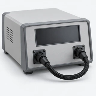
Continuity testing finds open connections; isolation testing detects unintended connections between circuits.
Where this fits
Combines motor, transmission and feedback to drive a robot joint.
Motor, strain-wave reducer, bearings, housing, encoder and drive form this rotary-joint architecture.
Sources & technical scope
Illustrative images of generic materials and components.
Related references
Mining and concentration produce a rare-earth feed for chemical processing.
Sequence: Ore extraction & concentration → Chemical upgrading.
Ore extraction & concentration
Mining and concentration produce a rare-earth feed for chemical processing.
Ore type determines the extraction and upgrading route.
Where this fits
Chemical processing prepares mixed rare-earth feed for separation into individual oxides.
Sources & technical scope
Illustrative images of generic materials and components.
Link to this detailChemical processing prepares mixed rare-earth feed for separation into individual oxides.
Sequence: Ore extraction & concentration → Chemical upgrading.
Sequence: Chemical upgrading → Rare-earth separation.
Chemical upgrading
Chemical processing prepares mixed rare-earth feed for separation into individual oxides.
Mining capacity alone does not provide oxide separation or magnet-making capacity.
Inputs & supporting parts
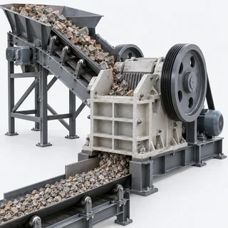
Mining and concentration produce a rare-earth feed for chemical processing.
Where this fits
Separation turns mixed rare-earth feeds into individual oxides.
Sources & technical scope
Illustrative images of generic materials and components.
Link to this detailA suitable coating protects corrosion-sensitive NdFeB material. Arnold offers epoxy and metallic coatings, with Parylene as another option.
Sequence: Magnet grinding & sizing → Protective magnet coating.
Production step for Permanent magnets: Protective magnet coating.
Related references
Protective magnet coating
A suitable coating protects corrosion-sensitive NdFeB material. Arnold offers epoxy and metallic coatings, with Parylene as another option.
Coating choice depends on environment and assembly requirements.
Inputs & supporting parts
After sintering and heat treatment, abrasive grinding or slicing brings the hard, brittle magnet body to its finished dimensions.
Where this fits
Provide the rotor field; grade and geometry must suit the motor.
Sources & technical scope
Illustrative images of generic materials and components.
Related references
An applied field magnetises the material in the required direction or pole pattern.
Production equipment for Magnetisation & pole pattern: Magnetising fixture.
Supporting dependency for Permanent magnets: Magnetisation & pole pattern.
This step
Related references
Magnetisation & pole pattern
An applied field magnetises the material in the required direction or pole pattern.
Magnetisation may occur before or after assembly; access and fixture design determine the sequence.
Inputs & supporting parts
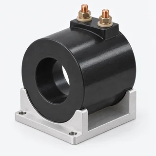
A coil or shaped fixture applies the magnetising field for the specified pole pattern.
Where this fits
Provide the rotor field; grade and geometry must suit the motor.
Sources & technical scope
Illustrative images of generic materials and components.
This step
Related references
A coil or shaped fixture applies the magnetising field for the specified pole pattern.
Production equipment for Magnetisation & pole pattern: Magnetising fixture.
This step
Magnetising fixture
A coil or shaped fixture applies the magnetising field for the specified pole pattern.
Where this fits
An applied field magnetises the material in the required direction or pole pattern.
Sources & technical scope
Illustrative images of generic materials and components.
This step
Link to this detailCopper rod supplies the conductor for this enamelled-wire route.
Material input to Wire drawing & annealing: Copper conductor stock.
Copper conductor stock
Copper rod supplies the conductor for this enamelled-wire route.
Copper is common; aluminium and other conductors are alternatives.
Where this fits
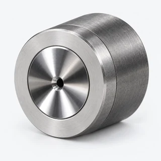
Drawing reduces the conductor diameter.
Sources & technical scope
Illustrative images of generic materials and components.
Link to this detailDrawing reduces the conductor diameter. Annealing restores softness for winding.
Material input to Wire drawing & annealing: Copper conductor stock.
Sequence: Wire drawing & annealing → Insulation coating & curing.
Wire drawing & annealing
Drawing reduces the conductor diameter. Annealing restores softness for winding.
Inputs & supporting parts
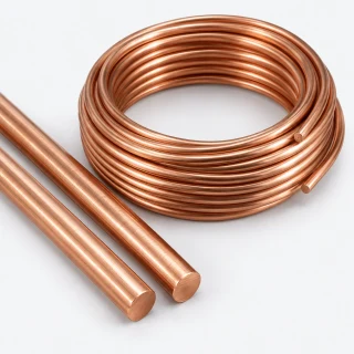
Copper rod supplies the conductor for this enamelled-wire route.
Where this fits
Thin enamel layers are applied and cured around the conductor.
Sources & technical scope
Illustrative images of generic materials and components.
Link to this detailThin enamel layers are applied and cured around the conductor.
Sequence: Wire drawing & annealing → Insulation coating & curing.
Production step for Insulated winding wire: Insulation coating & curing.
Insulation coating & curing
Thin enamel layers are applied and cured around the conductor.
Insulation must survive the winding process and operating temperature.
Inputs & supporting parts
Drawing reduces the conductor diameter.
Where this fits
Carries current through the stator coils; insulation separates adjacent turns.
Sources & technical scope
Illustrative images of generic materials and components.
Link to this detailThe finished wire combines an electrical conductor with turn-to-turn insulation.
Production step for Insulated winding wire: Insulation coating & curing.
Material input to Winding & assembly: Insulated winding wire.
Insulated winding wire
The finished wire combines an electrical conductor with turn-to-turn insulation.
Conductor and coating dimensions determine resistance and winding space.
Inputs & supporting parts
Thin enamel layers are applied and cured around the conductor.
Where this fits
Forms insulated conductors into stator coils.
Sources & technical scope
Illustrative images of generic materials and components.
Related references
Insulation coatings separate adjacent electrical-steel laminations; bonding coatings can also help retain the stack.
Material input to Laminated core: Electrical-steel insulation.
Related references
Electrical-steel insulation
Insulation coatings separate adjacent electrical-steel laminations; bonding coatings can also help retain the stack.
Specify the coating together with the steel grade and core production method.
Where this fits
Stacked electrical-steel sheets guide magnetic flux and limit eddy-current losses.
Sources & technical scope
Illustrative images of generic materials and components.
Related references
Gear components require a steel grade and heat treatment selected for their loads and manufacturing route.
Material input to Precision machining: Mechanical steel selection.
Related references
Mechanical steel selection
Gear components require a steel grade and heat treatment selected for their loads and manufacturing route.
Motor-core electrical steel serves a different function. A carburising grade for a rigid gear is not a universal flexspline specification.
Where this fits
Gear teeth and locating surfaces require controlled geometry.
Sources & technical scope
Illustrative images of generic materials and components.
Related references
Turning prepares the nut geometry before hardening in EMAG’s illustrated roller-screw process.
Sequence: Soft-machined nut blank → Nut heat treatment.
Soft-machined nut blank
Equipment-maker reference · EMAGTurning prepares the nut geometry before hardening in EMAG’s illustrated roller-screw process.
Equipment for this step →Where this fits
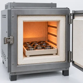
Hardening establishes the material condition before hard machining.
Sources & technical scope
Illustrative images of generic materials and components.
Link to this detailHardening establishes the material condition before hard machining.
Sequence: Soft-machined nut blank → Nut heat treatment.
Sequence: Nut heat treatment → Hard turning & thread finishing.
Nut heat treatment
Equipment-maker reference · EMAGHardening establishes the material condition before hard machining.
Hardness and dimensions are workpiece-specific.
Inputs & supporting parts
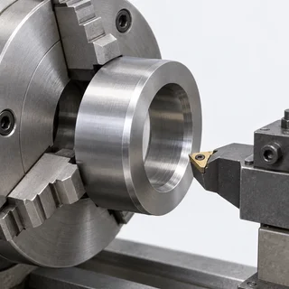
Turning prepares the nut geometry before hardening in EMAG’s illustrated roller-screw process.
Where this fits
Hard turning, external grinding and internal-thread finishing complete the nut’s precision surfaces.
Sources & technical scope
Illustrative images of generic materials and components.
Link to this detailHard turning, external grinding and internal-thread finishing complete the nut’s precision surfaces.
Sequence: Nut heat treatment → Hard turning & thread finishing.
Production step for Roller-screw nut: Hard turning & thread finishing.
Related references
Hard turning & thread finishing
Equipment-maker reference · EMAGHard turning, external grinding and internal-thread finishing complete the nut’s precision surfaces.
A deep bore restricts tool access and makes workholding significant.
Inputs & supporting parts
Hardening establishes the material condition before hard machining.
Where this fits
The nut surrounds the threaded roller arrangement and transfers axial load.
Sources & technical scope
Illustrative images of generic materials and components.
Related references
The input gear drives spur gears connected to crankshafts in Nabtesco’s two-stage RV arrangement.
Assembly input to Eccentric crankshafts: RV input spur stage.
RV input spur stage
The input gear drives spur gears connected to crankshafts in Nabtesco’s two-stage RV arrangement.
Where this fits
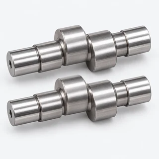
Crankshafts move the two RV gears eccentrically through needle bearings.
Sources & technical scope
Illustrative images of generic materials and components.
Link to this detailCrankshafts move the two RV gears eccentrically through needle bearings.
Assembly input to Eccentric crankshafts: RV input spur stage.
Assembly input to RV gears & case pins: Eccentric crankshafts.
Eccentric crankshafts
Crankshafts move the two RV gears eccentrically through needle bearings.
Inputs & supporting parts
The input gear drives spur gears connected to crankshafts in Nabtesco’s two-stage RV arrangement.
Where this fits
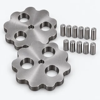
The RV gears engage pins arranged around the case; the pin count exceeds the gear tooth count by one.
Sources & technical scope
Illustrative images of generic materials and components.
Link to this detailThe RV gears engage pins arranged around the case; the pin count exceeds the gear tooth count by one.
Assembly input to RV gears & case pins: Eccentric crankshafts.
Used in RV reduction assembly: RV gears & case pins.
RV gears & case pins
The RV gears engage pins arranged around the case; the pin count exceeds the gear tooth count by one.
Inputs & supporting parts
Crankshafts move the two RV gears eccentrically through needle bearings.
Where this fits
The spur and pin-and-gear stages combine to reduce speed and transmit output torque.
Sources & technical scope
Illustrative images of generic materials and components.
Link to this detailThe spur and pin-and-gear stages combine to reduce speed and transmit output torque.
Used in RV reduction assembly: RV gears & case pins.
Design alternative for Rotary joint: RV reduction assembly.
Related references
RV reduction assembly
The spur and pin-and-gear stages combine to reduce speed and transmit output torque.
This is a cycloidal alternative to planetary and strain-wave reduction, not an extra stage required in every joint.
Inputs & supporting parts
The RV gears engage pins arranged around the case; the pin count exceeds the gear tooth count by one.
Where this fits
Combines motor, transmission and feedback to drive a robot joint.
Sources & technical scope
Illustrative images of generic materials and components.
Related references
Machined housing faces and bearing seats locate the joint parts. The housing also provides a heat path from the stator into the surrounding structure.
Sequence: Housing-interface machining → Housing & bearing seats.
Assembly input to Stator mounting & heat path: Housing & bearing seats.
Assembly input to Host motor integration: Housing & bearing seats.
Assembly input to Integrated rotary actuator: Housing & bearing seats.
Machined housing faces and bearing seats locate the joint parts. The housing also provides a heat path from the stator into the surrounding structure.
Inputs & supporting parts
Precision machining establishes mounting faces, bearing seats and motor location surfaces in the housing blank.
Where this fits
The wound stator is secured in a rigid housing that conducts heat away.
The host assembly supplies a housing, shaft support, bearings, feedback and drive around the frameless rotor and stator.
Motor, strain-wave reducer, bearings, housing, encoder and drive form this rotary-joint architecture.
Sources & technical scope
Illustrative images of generic materials and components.
This step
Related references
Rotor alignment establishes the motor air gap. Ground-continuity and wiring checks confirm the installed electrical connections before the drive is enabled.
Checks on Rotary joint: Alignment & electrical checks.
Checks on Host motor integration: Alignment & electrical checks.
Sequence: Rotary joint → Alignment & electrical checks.
Sequence: Alignment & electrical checks → Drive setup & motion checks.
Production step for Integrated rotary actuator: Alignment & electrical checks.
Alignment & electrical checks
Rotor alignment establishes the motor air gap. Ground-continuity and wiring checks confirm the installed electrical connections before the drive is enabled.
These installation checks cover alignment and electrical integrity. The cited installation guide does not establish a complete factory acceptance programme for the assembled actuator.
Inputs & supporting parts
Combines motor, transmission and feedback to drive a robot joint.
The host assembly supplies a housing, shaft support, bearings, feedback and drive around the frameless rotor and stator.
Where this fits
Motor parameters and feedback settings configure the drive.
Motor, strain-wave reducer, bearings, housing, encoder and drive form this rotary-joint architecture.
Sources & technical scope
Illustrative images of generic materials and components.
Related references
Motor parameters and feedback settings configure the drive. Position and phase checks establish that measured movement and motor rotation agree with the commanded direction.
Sequence: Alignment & electrical checks → Drive setup & motion checks.
Supporting dependency for Drive setup & motion checks: Position feedback.
Supporting dependency for Drive setup & motion checks: Servo electronics.
Drive setup & motion checks
Motor parameters and feedback settings configure the drive. Position and phase checks establish that measured movement and motor rotation agree with the commanded direction.
Commissioning establishes drive and feedback operation. Production acceptance limits require a separate test specification.
Inputs & supporting parts
Rotor alignment establishes the motor air gap.
An encoder reports position to the controller.
The drive supplies controlled motor current and closes feedback loops.
Sources & technical scope
Illustrative images of generic materials and components.
Related references
Laifual buys raw materials and uses outside partners for forging and some turning.
Sequence: Forged gear blanks → Heat treatment.
Forged gear blanks
Company disclosure · LaifualLaifual buys raw materials and uses outside partners for forging and some turning.
Where this fits
Annealing and normalising aid machining; quenching and tempering establish working hardness.
Sources & technical scope
Illustrative images of generic materials and components.
Link to this detailAnnealing and normalising aid machining; quenching and tempering establish working hardness. Laifual performs these stages in-house.
Sequence: Forged gear blanks → Heat treatment.
Sequence: Heat treatment → Precision machining.
Heat treatment
Company disclosure · LaifualAnnealing and normalising aid machining; quenching and tempering establish working hardness. Laifual performs these stages in-house.
Inputs & supporting parts
Laifual buys raw materials and uses outside partners for forging and some turning.
Where this fits
CNC lathes and machining centres shape the heat-treated blanks.
Sources & technical scope
Illustrative images of generic materials and components.
Link to this detailCNC lathes and machining centres shape the heat-treated blanks.
Sequence: Heat treatment → Precision machining.
Sequence: Precision machining → Reducer surface grinding.
Precision machining
Company disclosure · LaifualCNC lathes and machining centres shape the heat-treated blanks.
Inputs & supporting parts
Annealing and normalising aid machining; quenching and tempering establish working hardness.
Where this fits
Precision grinding finishes the part surfaces before gear machining in Laifual’s disclosed sequence.
Sources & technical scope
Illustrative images of generic materials and components.
Link to this detailPrecision grinding finishes the part surfaces before gear machining in Laifual’s disclosed sequence.
Sequence: Precision machining → Reducer surface grinding.
Sequence: Reducer surface grinding → Gear-tooth cutting.
Reducer surface grinding
Company disclosure · LaifualPrecision grinding finishes the part surfaces before gear machining in Laifual’s disclosed sequence.
Inputs & supporting parts
CNC lathes and machining centres shape the heat-treated blanks.
Where this fits
Gear machining creates the flexspline’s external teeth and circular spline’s internal teeth.
Sources & technical scope
Illustrative images of generic materials and components.
Link to this detailGear machining creates the flexspline’s external teeth and circular spline’s internal teeth.
Sequence: Reducer surface grinding → Gear-tooth cutting.
Production equipment for Gear-tooth cutting: Small-module gear cutters.
Checks on Gear-tooth cutting: Gear inspection.
Gear-tooth cutting
Company disclosure · LaifualGear machining creates the flexspline’s external teeth and circular spline’s internal teeth.
Inputs & supporting parts
Precision grinding finishes the part surfaces before gear machining in Laifual’s disclosed sequence.
Fine gear teeth require matching hobs, shaping cutters or skiving tools.
Where this fits
Gear measuring centres, coordinate measurement, roundness and contour checks precede assembly.
Sources & technical scope
Illustrative images of generic materials and components.
Related references
Gear measuring centres, coordinate measurement, roundness and contour checks precede assembly.
Checks on Gear-tooth cutting: Gear inspection.
Assembly input to Strain-wave reducer: Gear inspection.
Gear inspection
Company disclosure · LaifualGear measuring centres, coordinate measurement, roundness and contour checks precede assembly.
Inputs & supporting parts
Gear machining creates the flexspline’s external teeth and circular spline’s internal teeth.
Where this fits
Inspected parts enter the assembly line.
Sources & technical scope
Illustrative images of generic materials and components.
Link to this detailInspected parts enter the assembly line. Laifual also manufactures crossed-roller bearings for its own use.
Assembly input to Strain-wave reducer: Gear inspection.
Strain-wave reducer
Company disclosure · LaifualInspected parts enter the assembly line. Laifual also manufactures crossed-roller bearings for its own use.
Inputs & supporting parts
Gear measuring centres, coordinate measurement, roundness and contour checks precede assembly.
Sources & technical scope
Illustrative images of generic materials and components.
Link to this detailAfter assembly adjustment and grease filling, Seenpin tests the completed screw before warehousing.
Checks on Roller-screw assembly: Screw assembly testing.
Related references
Screw assembly testing
Company disclosure · SeenpinAfter assembly adjustment and grease filling, Seenpin tests the completed screw before warehousing.
Inputs & supporting parts
The assembled screw drive produces linear travel and force.
Sources & technical scope
Illustrative images of generic materials and components.
Related references
Stock for the shaft is rough-machined before heat treatment.
Sequence: Screw stock & rough machining → Heat treatment.
Screw stock & rough machining
Company disclosure · SeenpinStock for the shaft is rough-machined before heat treatment.
Where this fits
Heat treatment is followed by an inspection before thread formation.
Sources & technical scope
Illustrative images of generic materials and components.
Link to this detailHeat treatment is followed by an inspection before thread formation.
Sequence: Screw stock & rough machining → Heat treatment.
Sequence: Heat treatment → Thread formation & finishing.
Heat treatment
Company disclosure · SeenpinHeat treatment is followed by an inspection before thread formation.
Inputs & supporting parts
Stock for the shaft is rough-machined before heat treatment.
Where this fits
Thread formation follows heat treatment and inspection.
Sources & technical scope
Illustrative images of generic materials and components.
Link to this detailThread formation follows heat treatment and inspection. Seenpin identifies thread grinding and finishing among its core production processes.
Sequence: Heat treatment → Thread formation & finishing.
Checks on Thread formation & finishing: Thread inspection.
Thread formation & finishing
Company disclosure · SeenpinThread formation follows heat treatment and inspection. Seenpin identifies thread grinding and finishing among its core production processes.
Inputs & supporting parts
Heat treatment is followed by an inspection before thread formation.
Where this fits
The finished shaft is inspected before joining the other screw components at assembly.
Sources & technical scope
Illustrative images of generic materials and components.
Link to this detailThe finished shaft is inspected before joining the other screw components at assembly.
Checks on Thread formation & finishing: Thread inspection.
Production step for Threaded screw shaft: Thread inspection.
Related references
Thread inspection
Company disclosure · SeenpinThe finished shaft is inspected before joining the other screw components at assembly.
Inputs & supporting parts
Thread formation follows heat treatment and inspection.
Where this fits
The screw’s thread engages the threaded rollers in a planetary roller screw.
Sources & technical scope
Illustrative images of generic materials and components.
Related references
Stock for the rollers is rough-machined before heat treatment.
Sequence: Screw stock & rough machining → Heat treatment.
Screw stock & rough machining
Company disclosure · SeenpinStock for the rollers is rough-machined before heat treatment.
Where this fits
Heat treatment is followed by an inspection before thread formation.
Sources & technical scope
Illustrative images of generic materials and components.
Link to this detailHeat treatment is followed by an inspection before thread formation.
Sequence: Screw stock & rough machining → Heat treatment.
Sequence: Heat treatment → Thread formation & finishing.
Heat treatment
Company disclosure · SeenpinHeat treatment is followed by an inspection before thread formation.
Inputs & supporting parts
Stock for the rollers is rough-machined before heat treatment.
Where this fits
Thread formation follows heat treatment and inspection.
Sources & technical scope
Illustrative images of generic materials and components.
Link to this detailThread formation follows heat treatment and inspection. Seenpin identifies thread grinding and finishing among its core production processes.
Sequence: Heat treatment → Thread formation & finishing.
Checks on Thread formation & finishing: Thread inspection.
Thread formation & finishing
Company disclosure · SeenpinThread formation follows heat treatment and inspection. Seenpin identifies thread grinding and finishing among its core production processes.
Inputs & supporting parts
Heat treatment is followed by an inspection before thread formation.
Where this fits
The finished rollers is inspected before joining the other screw components at assembly.
Sources & technical scope
Illustrative images of generic materials and components.
Link to this detailThe finished rollers is inspected before joining the other screw components at assembly.
Checks on Thread formation & finishing: Thread inspection.
Production step for Threaded rollers: Thread inspection.
Related references
Thread inspection
Company disclosure · SeenpinThe finished rollers is inspected before joining the other screw components at assembly.
Inputs & supporting parts
Thread formation follows heat treatment and inspection.
Where this fits
Multiple threaded rollers transfer load between the screw and nut.
Sources & technical scope
Illustrative images of generic materials and components.
Related references
Stock for the nut is rough-machined before heat treatment.
Sequence: Screw stock & rough machining → Heat treatment.
Screw stock & rough machining
Company disclosure · SeenpinStock for the nut is rough-machined before heat treatment.
Where this fits
Heat treatment is followed by an inspection before thread formation.
Sources & technical scope
Illustrative images of generic materials and components.
Link to this detailHeat treatment is followed by an inspection before thread formation.
Sequence: Screw stock & rough machining → Heat treatment.
Sequence: Heat treatment → Thread formation & finishing.
Heat treatment
Company disclosure · SeenpinHeat treatment is followed by an inspection before thread formation.
Inputs & supporting parts
Stock for the nut is rough-machined before heat treatment.
Where this fits
Thread formation follows heat treatment and inspection.
Sources & technical scope
Illustrative images of generic materials and components.
Link to this detailThread formation follows heat treatment and inspection. Seenpin identifies thread grinding and finishing among its core production processes.
Sequence: Heat treatment → Thread formation & finishing.
Checks on Thread formation & finishing: Thread inspection.
Thread formation & finishing
Company disclosure · SeenpinThread formation follows heat treatment and inspection. Seenpin identifies thread grinding and finishing among its core production processes.
Inputs & supporting parts
Heat treatment is followed by an inspection before thread formation.
Where this fits
The finished nut is inspected before joining the other screw components at assembly.
Sources & technical scope
Illustrative images of generic materials and components.
Link to this detailThe finished nut is inspected before joining the other screw components at assembly.
Checks on Thread formation & finishing: Thread inspection.
Production step for Roller-screw nut: Thread inspection.
Related references
Thread inspection
Company disclosure · SeenpinThe finished nut is inspected before joining the other screw components at assembly.
Inputs & supporting parts
Thread formation follows heat treatment and inspection.
Where this fits
The nut surrounds the threaded roller arrangement and transfers axial load.
Sources & technical scope
Illustrative images of generic materials and components.
Related references
Direct Drive winds copper onto the stator core and checks coil height before electrical connections and board installation.
Checks on Winding & assembly: Stator electrical checks.
Winding & assembly
Company disclosure · Direct DriveDirect Drive winds copper onto the stator core and checks coil height before electrical connections and board installation.
Where this fits
The stator is inspected, phase connections soldered, bearings press-fitted and the control board installed.
Sources & technical scope
Illustrative images of generic materials and components.
Link to this detailThe stator is inspected, phase connections soldered, bearings press-fitted and the control board installed.
Checks on Winding & assembly: Stator electrical checks.
Checks on Winding & assembly: Stator electrical checks.
Assembly input to Rotor–stator assembly: Stator electrical checks.
Production step for Wound & checked stator: Stator electrical checks.
Related references
Stator electrical checks
Company disclosure · Direct DriveThe stator is inspected, phase connections soldered, bearings press-fitted and the control board installed.
Inputs & supporting parts
Forms insulated conductors into stator coils.
Forms insulated conductors into stator coils.
Where this fits
Rotor and stator are fitted together and retained.
The laminated core and insulated coils form the stator.
Sources & technical scope
Illustrative images of generic materials and components.
Related references
The shaft is bonded into the magnetic yoke. Magnets are attached to the yoke and the adhesive cures.
Assembly input to Rotor magnet bonding: Permanent magnets.
Assembly input to Rotor–stator assembly: Rotor magnet bonding.
Production step for Assembled rotor: Rotor magnet bonding.
Related references
Rotor magnet bonding
Company disclosure · Direct DriveThe shaft is bonded into the magnetic yoke. Magnets are attached to the yoke and the adhesive cures.
Inputs & supporting parts
Provide the rotor field; grade and geometry must suit the motor.
Where this fits
Rotor and stator are fitted together and retained.
The magnetic yoke, shaft and bonded magnets form the rotor.
Sources & technical scope
Illustrative images of generic materials and components.
Related references
Rotor and stator are fitted together and retained. Housing assembly and secured wiring complete the module.
Assembly input to Rotor–stator assembly: Stator electrical checks.
Assembly input to Rotor–stator assembly: Rotor magnet bonding.
Assembly input to Rotor–stator assembly: Assembled rotor.
Assembly input to Rotor–stator assembly: Wound & checked stator.
Rotor–stator assembly
Company disclosure · Direct DriveRotor and stator are fitted together and retained. Housing assembly and secured wiring complete the module.
Inputs & supporting parts
The stator is inspected, phase connections soldered, bearings press-fitted and the control board installed.
Bonds the shaft, magnetic yoke and magnets into a rotor assembly.
The magnetic yoke, shaft and bonded magnets form the rotor.
The laminated core and insulated coils form the stator.
Sources & technical scope
Illustrative images of generic materials and components.
Link to this detailStranded conductors, insulation and any shielding form the cable. Joint motion imposes bending and twisting loads on this construction.
Material input to Flexible cable stock: Torsion-resistant shielding.
Material input to Flexible cable stock: Buffer layers & jacket compounds.
Sequence: Flexible cable stock → Cable cutting & stripping.
Checks on Flexible cable stock: Bend & torsion qualification.
Related references
Flexible cable stock
Stranded conductors, insulation and any shielding form the cable. Joint motion imposes bending and twisting loads on this construction.
Inputs & supporting parts
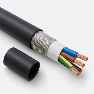
In igus CF Robot cables, a tin-plated copper shield and sliding layers accommodate torsion.
The igus example uses rayon, PTFE or filling elements to absorb torsional loads, with PUR or TPE outer sheathing.
Where this fits
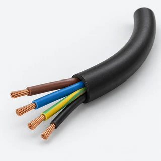
Wire is cut to length and insulation removed at the ends.
Repeated-motion tests assess the cable construction under defined bending or twisting conditions.
Sources & technical scope
Illustrative images of generic materials and components.
Related references
Wire is cut to length and insulation removed at the ends. Strip inspection detects damaged strands or insulation remaining at the termination.
Sequence: Flexible cable stock → Cable cutting & stripping.
Sequence: Cable cutting & stripping → Terminal crimping.
Cable cutting & stripping
Wire is cut to length and insulation removed at the ends. Strip inspection detects damaged strands or insulation remaining at the termination.
Inputs & supporting parts
Stranded conductors, insulation and any shielding form the cable.
Where this fits
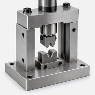
A terminal-specific tool compresses the contact around the conductor.
Sources & technical scope
Illustrative images of generic materials and components.
Related references
A terminal-specific tool compresses the contact around the conductor. Wire size, terminal geometry and crimp height determine the connection.
Sequence: Cable cutting & stripping → Terminal crimping.
Production equipment for Terminal crimping: Crimp applicator.
Sequence: Terminal crimping → Connector contact insertion.
Checks on Terminal crimping: Crimp quality checks.
Terminal crimping
A terminal-specific tool compresses the contact around the conductor. Wire size, terminal geometry and crimp height determine the connection.
Inputs & supporting parts
Wire is cut to length and insulation removed at the ends.
The applicator forms the terminal to its specified profile.
Where this fits
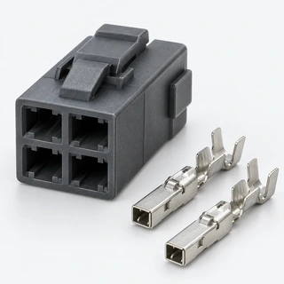
Crimped contacts lock into their assigned connector cavities.
Crimp height and force monitoring track the termination process.
Sources & technical scope
Illustrative images of generic materials and components.
Related references
Crimp height and force monitoring track the termination process. Sample pull tests measure mechanical retention; over-compression can damage strands.
Checks on Terminal crimping: Crimp quality checks.
Crimp quality checks
Crimp height and force monitoring track the termination process. Sample pull tests measure mechanical retention; over-compression can damage strands.
Inputs & supporting parts
A terminal-specific tool compresses the contact around the conductor.
Sources & technical scope
Illustrative images of generic materials and components.
Link to this detailCrimped contacts lock into their assigned connector cavities. The connector’s retention system holds the contacts in position.
Sequence: Terminal crimping → Connector contact insertion.
Sequence: Connector contact insertion → Harness branching & retention.
Connector contact insertion
Crimped contacts lock into their assigned connector cavities. The connector’s retention system holds the contacts in position.
Inputs & supporting parts
A terminal-specific tool compresses the contact around the conductor.
Where this fits
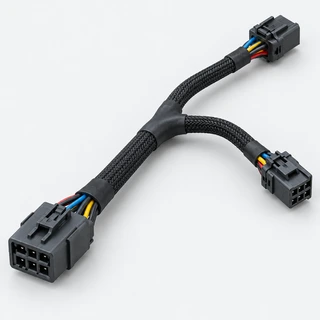
Prepared leads form the harness layout.
Sources & technical scope
Illustrative images of generic materials and components.
Related references
Prepared leads form the harness layout. Twisting and taping group the specified wires and secure the branches.
Sequence: Connector contact insertion → Harness branching & retention.
Sequence: Harness branching & retention → Harness electrical test.
Harness branching & retention
Prepared leads form the harness layout. Twisting and taping group the specified wires and secure the branches.
Inputs & supporting parts
Crimped contacts lock into their assigned connector cavities.
Where this fits
Continuity testing finds open connections; isolation testing detects unintended connections between circuits.
Sources & technical scope
Illustrative images of generic materials and components.
This step
Related references
Continuity testing finds open connections; isolation testing detects unintended connections between circuits. The test programme defines the intended wiring and acceptance limits.
Sequence: Harness branching & retention → Harness electrical test.
Sequence: Harness electrical test → Lead routing & grounding.
Harness electrical test
Continuity testing finds open connections; isolation testing detects unintended connections between circuits. The test programme defines the intended wiring and acceptance limits.
Inputs & supporting parts
Prepared leads form the harness layout.
Where this fits
Phase, temperature-sensor and feedback wiring connects the motor to its drive.
Sources & technical scope
Illustrative images of generic materials and components.
Related references
Repeated-motion tests assess the cable construction under defined bending or twisting conditions. Twist angle, free cable length and cycle count describe the test.
Checks on Flexible cable stock: Bend & torsion qualification.
Bend & torsion qualification
Repeated-motion tests assess the cable construction under defined bending or twisting conditions. Twist angle, free cable length and cycle count describe the test.
Inputs & supporting parts
Stranded conductors, insulation and any shielding form the cable.
Sources & technical scope
Illustrative images of generic materials and components.
Link to this detailThe applicator forms the terminal to its specified profile. Tool wear and wire placement affect the resulting connection.
Production equipment for Terminal crimping: Crimp applicator.
Crimp applicator
The applicator forms the terminal to its specified profile. Tool wear and wire placement affect the resulting connection.
Where this fits
A terminal-specific tool compresses the contact around the conductor.
Sources & technical scope
Illustrative images of generic materials and components.
Link to this detailIn igus CF Robot cables, a tin-plated copper shield and sliding layers accommodate torsion. A conventional braided shield is not the same construction.
Material input to Flexible cable stock: Torsion-resistant shielding.
Torsion-resistant shielding
In igus CF Robot cables, a tin-plated copper shield and sliding layers accommodate torsion. A conventional braided shield is not the same construction.
Where this fits
Stranded conductors, insulation and any shielding form the cable.
Sources & technical scope
Illustrative images of generic materials and components.
Link to this detailThe igus example uses rayon, PTFE or filling elements to absorb torsional loads, with PUR or TPE outer sheathing. These are cable-construction choices, not interchangeable jacket labels.
Material input to Flexible cable stock: Buffer layers & jacket compounds.
Buffer layers & jacket compounds
The igus example uses rayon, PTFE or filling elements to absorb torsional loads, with PUR or TPE outer sheathing. These are cable-construction choices, not interchangeable jacket labels.
Where this fits
Stranded conductors, insulation and any shielding form the cable.
Sources & technical scope
Illustrative images of generic materials and components.
Link to this detailTolomatic describes grinding, rolling and whirling as different roller-screw manufacturing routes. Internal-thread grinding of inverted nuts is possible but raises manufacturing cost in its comparison.
Supporting dependency for Roller-screw nut: Thread process & acceptance grade.
Related references
Thread process & acceptance grade
Tolomatic describes grinding, rolling and whirling as different roller-screw manufacturing routes. Internal-thread grinding of inverted nuts is possible but raises manufacturing cost in its comparison.
Supplier qualification needs the actual finishing route, heat treatment and achieved accuracy. The architecture label alone does not establish equivalent performance.
Where this fits
The nut surrounds the threaded roller arrangement and transfers axial load.
Sources & technical scope
Illustrative images of generic materials and components.
Related references
Tolomatic’s catalogue specifies lead accuracy of 0.023 mm per 300 mm and backlash of 0.03 mm for its listed screws. These describe different acceptance characteristics.
Checks on Roller-screw assembly: Lead accuracy & backlash acceptance.
Related references
Lead accuracy & backlash acceptance
Tolomatic’s catalogue specifies lead accuracy of 0.023 mm per 300 mm and backlash of 0.03 mm for its listed screws. These describe different acceptance characteristics.
These are a catalogue example, not universal robot requirements. A substitute must meet the drawing’s lead accuracy and clearance or preload specification, as well as its load rating.
Inputs & supporting parts
The assembled screw drive produces linear travel and force.
Sources & technical scope
Illustrative images of generic materials and components.
Related references
Fine gear teeth require matching hobs, shaping cutters or skiving tools. Hengfeng’s filing describes carbide cutters for internal and external robot-reducer gears.
Production equipment for Gear-tooth cutting: Small-module gear cutters.
Small-module gear cutters
Fine gear teeth require matching hobs, shaping cutters or skiving tools. Hengfeng’s filing describes carbide cutters for internal and external robot-reducer gears.
Internal gears and obstructed tool access can favour skiving over hobbing.
Where this fits
Gear machining creates the flexspline’s external teeth and circular spline’s internal teeth.
Sources & technical scope
Illustrative images of generic materials and components.
This step
Related references
The magnetic yoke, shaft and bonded magnets form the rotor. Adhesive cure and magnet retention precede rotor–stator assembly in the Direct Drive example.
Production step for Assembled rotor: Rotor magnet bonding.
Assembly input to Rotor–stator assembly: Assembled rotor.
Assembly input to Frameless motor: Assembled rotor.
Assembly input to Host motor integration: Assembled rotor.
Assembled rotor
Company disclosure · Direct DriveThe magnetic yoke, shaft and bonded magnets form the rotor. Adhesive cure and magnet retention precede rotor–stator assembly in the Direct Drive example.
Inputs & supporting parts
Bonds the shaft, magnetic yoke and magnets into a rotor assembly.
Where this fits
Rotor and stator are fitted together and retained.
Rotor and stator supply torque within the joint; bearings, feedback and cooling complete the installation.
The host assembly supplies a housing, shaft support, bearings, feedback and drive around the frameless rotor and stator.
Sources & technical scope
Illustrative images of generic materials and components.
Related references
The laminated core and insulated coils form the stator. Electrical connections and stator inspection precede joining it to the rotor.
Production step for Wound & checked stator: Stator electrical checks.
Assembly input to Rotor–stator assembly: Wound & checked stator.
Assembly input to Frameless motor: Wound & checked stator.
Assembly input to Host motor integration: Wound & checked stator.
Wound & checked stator
Company disclosure · Direct DriveThe laminated core and insulated coils form the stator. Electrical connections and stator inspection precede joining it to the rotor.
Inputs & supporting parts
The stator is inspected, phase connections soldered, bearings press-fitted and the control board installed.
Where this fits
Rotor and stator are fitted together and retained.
Rotor and stator supply torque within the joint; bearings, feedback and cooling complete the installation.
The host assembly supplies a housing, shaft support, bearings, feedback and drive around the frameless rotor and stator.
Sources & technical scope
Illustrative images of generic materials and components.
Related references
The host assembly supplies a housing, shaft support, bearings, feedback and drive around the frameless rotor and stator. These are separate integration dependencies.
Assembly input to Host motor integration: Housing & bearing seats.
Assembly input to Host motor integration: Assembled rotor.
Assembly input to Host motor integration: Wound & checked stator.
Checks on Host motor integration: Alignment & electrical checks.
Host motor integration
The host assembly supplies a housing, shaft support, bearings, feedback and drive around the frameless rotor and stator. These are separate integration dependencies.
Inputs & supporting parts
Machined housing faces and bearing seats locate the joint parts.
The magnetic yoke, shaft and bonded magnets form the rotor.
The laminated core and insulated coils form the stator.
Where this fits
Rotor alignment establishes the motor air gap.
Sources & technical scope
Illustrative images of generic materials and components.
This step
Related references
Metal stock or a near-net-shape blank supplies the housing. Its material and geometry follow the joint design.
Sequence: Housing stock → Housing-interface machining.
Housing stock
Equipment-maker reference · GROBMetal stock or a near-net-shape blank supplies the housing. Its material and geometry follow the joint design.
Where this fits
Precision machining establishes mounting faces, bearing seats and motor location surfaces in the housing blank.
Sources & technical scope
Illustrative images of generic materials and components.
Link to this detailPrecision machining establishes mounting faces, bearing seats and motor location surfaces in the housing blank. Dimensional inspection precedes assembly.
Sequence: Housing stock → Housing-interface machining.
Sequence: Housing-interface machining → Housing & bearing seats.
Housing-interface machining
Equipment-maker reference · GROBPrecision machining establishes mounting faces, bearing seats and motor location surfaces in the housing blank. Dimensional inspection precedes assembly.
Equipment for this step →Inputs & supporting parts
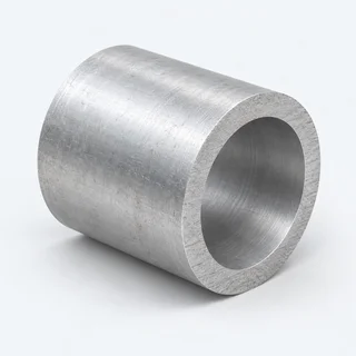
Metal stock or a near-net-shape blank supplies the housing.
Where this fits
Machined housing faces and bearing seats locate the joint parts.
Sources & technical scope
Illustrative images of generic materials and components.
Link to this detailA motor drive needs a circuit board, power switches, control components and connectors. Position feedback and wiring are separate assembly inputs.
Sequence: Board & electronic components → Drive-board assembly.
Board & electronic components
A motor drive needs a circuit board, power switches, control components and connectors. Position feedback and wiring are separate assembly inputs.
Where this fits
Bare boards, power switches, control ICs and connectors become the drive through component placement, soldering and inspection.
Sources & technical scope
Illustrative images of generic materials and components.
This step
Related references
Bare boards, power switches, control ICs and connectors become the drive through component placement, soldering and inspection. Feedback devices and harnesses remain separate inputs.
Sequence: Board & electronic components → Drive-board assembly.
Sequence: Drive-board assembly → Servo electronics.
Drive-board assembly
Bare boards, power switches, control ICs and connectors become the drive through component placement, soldering and inspection. Feedback devices and harnesses remain separate inputs.
Equipment for this step →Inputs & supporting parts
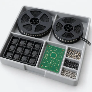
A motor drive needs a circuit board, power switches, control components and connectors.
Where this fits
The drive supplies controlled motor current and closes feedback loops.
Sources & technical scope
Illustrative images of generic materials and components.
This step
Related references
Motor, strain-wave reducer, bearings, housing, encoder and drive form this rotary-joint architecture. Brakes and alternative reductions depend on the design.
Production step for Integrated rotary actuator: Alignment & electrical checks.
Assembly input to Integrated rotary actuator: Frameless motor.
Assembly input to Integrated rotary actuator: Position feedback.
Assembly input to Integrated rotary actuator: Servo electronics.
Assembly input to Integrated rotary actuator: Bearing support.
Assembly input to Integrated rotary actuator: Strain-wave reducer.
Assembly input to Integrated rotary actuator: Housing & bearing seats.
Supporting dependency for Integrated rotary actuator: Lead routing & grounding.
This step
Related references
Integrated rotary actuator
Motor, strain-wave reducer, bearings, housing, encoder and drive form this rotary-joint architecture. Brakes and alternative reductions depend on the design.
Inputs & supporting parts
Rotor alignment establishes the motor air gap.
Rotor and stator supply torque within the joint; bearings, feedback and cooling complete the installation.
An encoder reports position to the controller.
The drive supplies controlled motor current and closes feedback loops.
Bearings carry radial, axial and moment loads and locate the moving assembly.
The assembled reduction stage trades motor speed for joint torque.
Machined housing faces and bearing seats locate the joint parts.
Phase, temperature-sensor and feedback wiring connects the motor to its drive.
Sources & technical scope
Illustrative images of generic materials and components.
This step
Related references
Production equipment
- GROBWinding & insertion systems
Forms motor windings and inserts coils into stators. Equipment configuration follows the winding method and stator geometry.
Coil winding →EuropeSources
Motor stators · coil formation and insertion
GROB · motor production systems - NITTOKUMotor winding machines
Inner, outer-rotor and segmented-core winding machines form coils for different motor constructions.
- Gleason80PS gear-cutting machine
Power skiving, hobbing and profile milling produce small internal and external gears for strain-wave, planetary and cycloidal reducers.
- Gleason175GMS nano metrology
Scanning probes measure gear geometry and surface roughness. Measurements support inspection of small precision gearboxes.
Gear inspection →United StatesSources
Joint reducers · gear geometry and surface inspection
Gleason · 175GMS nano - EMAGRoller-screw nut machining
EMAG’s example combines soft turning, heat treatment, hard machining and internal-thread grinding to finish roller-screw nuts.
Turning & thread grinding →EuropeSources
Linear actuators · finished roller-screw nuts
EMAG · nut production sequence - NETZSCHRare-earth alloy jet mills
Inert-gas jet milling and classification produce fine NdFeB alloy powder with a controlled particle-size distribution.
Magnet powder preparation →EuropeSources
Permanent-magnet motors · NdFeB alloy powder
NETZSCH · rare-earth alloy processing - Hanwha SemitechSMT component-placement machines
Chip mounters place electronic components on circuit boards before soldering. The populated boards form motor drives and onboard computers.
PCB component placement →South KoreaSources
Motor drives and compute · populated circuit boards
Hanwha Semitech · SMT equipmentHanwha · Semitech name change - KezhixinInternal and external thread grinders
Internal-thread grinders finish roller-screw nuts; external-thread machines finish screw shafts and rollers. Shuanglin reported a new Kezhixin factory opening in June 2026, with planned capacity above 40 machines a month.
Thread grinding →ChinaSources
Linear actuators · screw shafts, rollers and nuts
Shuanglin · Kezhixin equipment and factory update - Mitsui SeikiPrecision thread grinders
Mitsui Seiki makes external- and internal-thread grinders for precision screws. Its GSE30A external-thread machine lists a maximum grinding length of 300 mm.
- SupfinaBearing-raceway finishing machines
Superfinishing machines improve bearing raceway surfaces after grinding. The finish controls friction, lubrication and wear at the rolling contact.
Raceway grinding & finishing →EuropeSources
Joint bearings · finished ring raceways
Supfina · bearing-ring and rolling-element machining - DMG MORIFive-axis machining centres
Five-axis machining cuts housing interfaces, mounting faces and complex tooling. The same machine class produces structural parts and moulds from solid stock.
Precision machining →Sources
Actuator housings and robot structures · machined interfaces and tooling
DMG MORI · structural components, housings and die-and-mould machining





Market context
Unitree · quadruped production and sales

26,032Quadrupeds produced · 2025
23,037Quadrupeds sold · 2025
Annual production and recognised sales of quadruped robots.
Lens · DOBOT assembly and component order

10,000Rover X1 robots · assembly order
Complete-machine assembly order for Rover X1.
Rare-earth magnets
China · global sintered-magnet output94%
China · global magnet rare-earth refining91%
Global supply across industries. Refining and finished magnets are separate dependencies for permanent-magnet motors.
Direct Drive

Direct Drive Tech shipped 12,878 embodied joint modules in H1 2026, up from 3,898 a year earlier. Average selling price fell from RMB763 to RMB257 as its product mix broadened across price points.
Unitree
Unitree assembles robots and core modules internally. It buys custom mechanical parts and outsources most PCB assembly, injection moulding and some machining.
MEVIUS2 · twelve purchased joint motors
MEVIUS2 uses twelve RobStride03 motors. Its open parts list combines purchased actuator modules with separately fabricated links and housings.
maxon

ANYbotics assigned development and production of ANYmal actuators to maxon. Each robot uses twelve drive systems; the agreement moved the actuator programme from small-series development toward industrial production.
Companies
Browse components →maxonSupply connection · ANYboticsCubeMarsAK70-10 KV100Direct Drive TechP1010 and HMC joint modulesJiangsu LeiliSupply connection · Nanjing Weilan TechnologyLens TechnologyRover X1 assembly & componentsUnitreeCaptive joint production
Explore documented supply relationships →

Frameless motors
Rotor and stator sets designed to be integrated into a joint housing. The surrounding bearings, transmission and cooling are separate design choices.
Inside a frameless motor
Explore the stationary stator and rotating magnet assembly. Bearings, housing and transmission belong to the surrounding joint design.
Drag to rotate · pinch / scroll to zoom
Loading model…
Stator and rotor
The wound stator surrounds a permanent-magnet rotor. Their magnetic interaction produces torque across a small air gap.
Explore componentAbout this model
Original Korthos illustrative geometry, not a manufacturer’s product or manufacturing CAD. The windings and magnets are simplified. Dimensions, pole arrangement and winding layout do not specify a validated electromagnetic design.
Model scope & reuseArchitecture, materials & specificationsArchitecture options, material requirements and integration constraints
Architecture options
Slotted versus slotless describes the stator. Inner versus outer rotor is a separate packaging choice.
| Approach | Mechanism | Advantages | Trade-offs |
|---|---|---|---|
| Slotted stator | Windings sit around steel teeth that guide magnetic flux. | Can produce high torque within a compact motor. | Tooth-to-magnet attraction can create cogging: small torque variations as the rotor turns. |
| Slotless stator | Windings sit in the air gap without stator teeth. | Avoids tooth-related cogging for smooth low-speed motion. | Torque density and winding heat removal constrain the available joint package. |
| Inner rotor | The rotor turns inside the stator. | Places the stator near the housing, providing a direct heat path. | The rotor has a smaller working radius; bearings and wiring still need space. |
| Outer rotor | The rotor turns around the stator. | A larger working radius can increase torque for a given tangential force. | Rotating mass, clearance and the heat path from the inner stator constrain integration. |
Specifications & operating limits
Continuous torque describes sustained twisting effort under stated cooling conditions. The torque constant relates current to torque. Outer diameter, length and bore describe the space occupied by the motor.
Materials & constraints
- Copper windings
- More current produces more torque but also more resistive heating. Wire area, winding arrangement and the heat path through the stator constrain sustained output; the surrounding robot housing becomes part of the thermal design.
- Laminated electrical steel
- Thin insulated steel sheets guide magnetic flux while limiting circulating eddy currents. Lamination thickness, magnetic saturation and the frequency of the changing field influence loss, heating and torque density.
- NdFeB permanent magnets
- Many permanent-magnet motors use neodymium-iron-boron for strong magnetic fields in a small volume. Grade, temperature resistance, corrosion protection and rotor retention constrain motor performance.
- Insulation, resin & adhesives
- These electrically isolate and secure the windings and magnets. Their temperature limits and ageing behaviour can constrain the assembly before the metal parts do. Impregnation and thermal contact provide heat paths.
Dependencies & engineering limits
- Housing & continuous torque
- The stator needs accurate mounting and a heat path into the housing. Nearby gearing, bearings or encoders may reach their temperature limits before the winding does. The lowest thermal limit in the assembled joint constrains sustained torque. Structure & materials
- Assembly & air gap
- Bearings and accurately located mounting surfaces keep the rotor centred. Load and temperature changes can alter that air gap through movement or expansion of the surrounding structure. Bearings
- Feedback & usable control
- The drive uses rotor-position feedback to control motor current. Encoder mounting error can limit control quality before the motor reaches its mechanical limits. Encoders & position sensors
- Magnet supply
- A permanent-magnet rotor uses a specified magnet grade, shape and temperature capability. Changing the magnet can require electromagnetic redesign and thermal testing.
Manufacturing & assembly
Parts & processes
No matching parts or examples.
Representative industrial route. Permanent magnets, electrical steel and insulated copper feed separate rotor and stator production. These two parts are the frameless motor; housing, bearings, feedback and drive are supplied by the host assembly.
Rotor
Stator
Other routes
Manufacturing · Representative route. A sintered NdFeB, permanent-magnet motor route.
Related parts & processes 8
Manufacturing · Representative route. Magnetic core production and conductor winding meet in the motor.
Related parts & processes 5
Integration / calibration · Representative route. Rotor and stator integrate with the housing, bearings and drive.
Related parts & processes 5
Manufacturing · Representative route. A primary rare-earth route; each stage needs its own industrial capability.
Manufacturing · Representative route. Coating and magnetisation are separate dependencies; the assembly determines their sequence.
Related parts & processes 3
Manufacturing · Representative route. A wire-production route feeding stator assembly alongside the laminated core.
Related parts & processes 2
Integration / calibration · Representative route. Rotor, stator, housing and bearings meet at installation, followed by electrical checks and drive commissioning.
Related parts & processes 5
Assembly · Company-disclosed process · Direct Drive. A disclosed factory assembly sequence. PCB surface mounting is among the supplementary processes contracted out.
Related parts & processes 4
Assembly · Representative route. Cable preparation, termination and electrical testing feed the motor’s power and feedback connections.
Related parts & processes 5
Assembly · Representative route. A bonded permanent-magnet rotor; stator manufacture runs in parallel.
Related parts & processes 2
Manufacturing · Representative route. The housing is made separately from the motor and bought-in bearings.
Related parts & processes 1
Assembly · Representative route. Rotor and stator are supplied as separate parts for host integration.
Related parts & processes 1
Alloy composition sets the balance between magnetic strength and temperature capability.
Material input to NdFeB alloy: Metals & alloy feed.
Material input to Alloy casting & powder preparation: NdFeB alloy.
NdFeB alloy
Neodymium, iron and boron form the magnetic alloy in this sintered-magnet route. Grade selection trades magnetic performance against temperature requirements.
Heavy-rare-earth additions vary by grade.
Inputs & supporting parts
Refined oxides are converted into metals that feed magnet alloy production.
Where this fits
Cast alloy becomes powder through crushing and milling.
Sources & technical scope
Illustrative images of generic materials and components.
This step
Related references
Powder alignment, pressing and sintering form a magnet body with the required geometry and magnetic properties.
Sequence: Powder alignment & pressing → Pressing & sintering.
Sequence: Alloy casting & powder preparation → Pressing & sintering.
Production step for Permanent magnets: Pressing & sintering.
Sequence: Pressing & sintering → Magnet grinding & sizing.
94% China share · Global sintered permanent-magnet production · 2024
Across industries; not a robotics-specific share. Mining and refining are separate supply stages.
Pressing & sintering
Powder processing, alignment, pressing and sintering create the magnet material. Pressing route and alloy composition affect its magnetic properties.
Inputs & supporting parts
A magnetic field aligns powder particles; pressure compacts the powder into a body for sintering.
Cast alloy becomes powder through crushing and milling.
Where this fits
Provide the rotor field; grade and geometry must suit the motor.
After sintering and heat treatment, abrasive grinding or slicing brings the hard, brittle magnet body to its finished dimensions.
Sources & technical scope
Illustrative images of generic materials and components.
Related references
Permanent magnets provide the rotor field. Their grade, shape and retention are selected for the motor’s temperature and speed.
Production step for Permanent magnets: Pressing & sintering.
Possible production process for Permanent magnets: Grain-boundary diffusion.
Production step for Permanent magnets: Protective magnet coating.
Supporting dependency for Permanent magnets: Magnetisation & pole pattern.
Used in Frameless motor: Permanent magnets.
Used in Rotor mounting & air gap: Permanent magnets.
Assembly input to Rotor magnet bonding: Permanent magnets.
94% China share · Global sintered permanent-magnet production · 2024
Across industries; not a robotics-specific share. Mining and refining are separate supply stages.
This step
Related references
US DOE - magnet production stages (2022 technical reference, section 2.2)Kollmorgen · TBM2GTDK - HAL grain-boundary diffusionYunsheng · application proof, pp. 131–132Kollmorgen - frameless rotor/stator installationArnold · NdFeB grades and protective coatingsArnold · magnetisation and fixturesDirect Drive Tech · prospectus, pp. 163–164
Industrial significance
Permanent magnets
Finished magnets provide the rotor magnetic field in this permanent-magnet motor architecture. Their dimensions, grade and retention must suit the motor.
Inputs & supporting parts
Aligns and consolidates alloy powder into the magnet material.
A dysprosium- or terbium-bearing layer is applied to the magnet and diffused by heat treatment.
A suitable coating protects corrosion-sensitive NdFeB material.
An applied field magnetises the material in the required direction or pole pattern.
Where this fits
Rotor and stator supply torque within the joint; bearings, feedback and cooling complete the installation.
Locates the rotor relative to the stator and sets clearance between their magnetic surfaces.
Bonds the shaft, magnetic yoke and magnets into a rotor assembly.
Examples from industry 1
GenericSintered NdFeB magnets add alloy preparation, powder processing, pressing and sintering to the motor supply chain. Temperature capability and heavy-rare-earth content vary by grade.
Sources & technical scope
Illustrative images of generic materials and components.
This step
Related references
US DOE - magnet production stages (2022 technical reference, section 2.2)Kollmorgen · TBM2GTDK - HAL grain-boundary diffusionYunsheng · application proof, pp. 131–132Kollmorgen - frameless rotor/stator installationArnold · NdFeB grades and protective coatingsArnold · magnetisation and fixturesDirect Drive Tech · prospectus, pp. 163–164
The joint housing locates the frameless rotor and stator and provides bearing support, cooling and feedback.
Used in Frameless motor: Permanent magnets.
Production step for Frameless motor: Winding & assembly.
Supporting dependency for Frameless motor: Servo electronics.
Assembly input to Frameless motor: Assembled rotor.
Assembly input to Frameless motor: Wound & checked stator.
Assembly input to Stator mounting & heat path: Frameless motor.
Frameless motor
Rotor and stator are integrated into the joint structure. Bearings, sensing, drive electronics and thermal management complete the installation.
Continuous torque depends on cooling and operating conditions.
Inputs & supporting parts
Provide the rotor field; grade and geometry must suit the motor.
Forms insulated conductors into stator coils.
The drive supplies controlled motor current and closes feedback loops.
The magnetic yoke, shaft and bonded magnets form the rotor.
The laminated core and insulated coils form the stator.
Where this fits
The wound stator is secured in a rigid housing that conducts heat away.
Examples from industry 1
GenericA frameless motor supplies the electromagnetics. The joint still needs a housing, bearing support, feedback and a thermal path. Continuous performance depends on the installed cooling and operating conditions.
Sources & technical scope
Illustrative images of generic materials and components.
This step
Related references
Electrical steel carries magnetic flux in the motor core. Grade and processing affect magnetic losses and mechanical properties.
Material input to Laminated core: Electrical steel.
This step
Electrical steel
Non-grain-oriented electrical steel supplies magnetic core material for motors. Magnetic losses and material homogeneity matter alongside mechanical properties.
Where this fits
Stacked electrical-steel sheets guide magnetic flux and limit eddy-current losses.
Examples from industry 1
GenericNon-grain-oriented electrical steel is an input to motor cores. Magnetic properties and losses guide grade selection. voestalpine offers grades for motor applications.
Sources & technical scope
Illustrative images of generic materials and components.
This step
Link to this detailElectrical-steel laminations are formed and stacked to create the motor core. Grade, geometry and processing affect magnetic performance.
Material input to Laminated core: Electrical steel.
Material input to Laminated core: Electrical-steel insulation.
Assembly input to Winding & assembly: Laminated core.
Laminated core
Electrical-steel laminations form the motor’s magnetic core. Material grade and processing affect magnetic performance.
Inputs & supporting parts
Non-grain-oriented electrical steel supplies magnetic core material for motors.
Insulation coatings separate adjacent electrical-steel laminations; bonding coatings can also help retain the stack.
Where this fits
Forms insulated conductors into stator coils.
Examples from industry 1
GenericGodrej documents stamped laminations, stator stacks and rotor assemblies, including custom stack heights and slot geometries. This adds tooling and core assembly between electrical steel and a finished motor.
Sources & technical scope
Illustrative images of generic materials and components.
This step
Related references
Winding and insertion equipment forms and places coils in the stator. Tooling follows the slot geometry and assembly sequence.
Assembly input to Winding & assembly: Laminated core.
Production equipment for Winding & assembly: Winding equipment.
Material input to Winding & assembly: Insulated winding wire.
Production step for Frameless motor: Winding & assembly.
Assembly input to Stator mounting & heat path: Winding & assembly.
Checks on Winding & assembly: Stator electrical checks.
Winding & assembly
Equipment-maker reference · GROBConductors are formed into coils and assembled into the stator. Winding and insertion methods depend on the slots, coil geometry and assembly sequence.
The winding method and tooling must suit the stator geometry.
Inputs & supporting parts
Stacked electrical-steel sheets guide magnetic flux and limit eddy-current losses.
Winding machines form coils; insertion and assembly systems place them in the stator.
Carries current through the stator coils; insulation separates adjacent turns.
Where this fits
Rotor and stator supply torque within the joint; bearings, feedback and cooling complete the installation.
The wound stator is secured in a rigid housing that conducts heat away.
The stator is inspected, phase connections soldered, bearings press-fitted and the control board installed.
Examples from industry 1
GenericNeedle, flyer and linear winding are different ways to form motor coils. Winding, insertion and assembly equipment must match the stator geometry.
Sources & technical scope
Illustrative images of generic materials and components.
Related references
Winding machines form coils; insertion and assembly systems place them in the stator.
Production equipment for Winding & assembly: Winding equipment.
Winding equipment
Equipment-maker reference · GROBWinding machines form coils; insertion and assembly systems place them in the stator.
Equipment for this step →Where this fits
Forms insulated conductors into stator coils.
Sources & technical scope
Illustrative images of generic materials and components.
Link to this detailAn encoder reports position to the controller. Motor-side and output-side feedback observe different points in the transmission.
Supporting dependency for Lead routing & grounding: Position feedback.
Supporting dependency for Drive setup & motion checks: Position feedback.
Position feedback
Encoders & position sensors →An encoder reports position to the controller. Motor-side and output-side feedback observe different points in the transmission.
Installed accuracy depends on mounting error and mechanical deflection.
Where this fits
Phase, temperature-sensor and feedback wiring connects the motor to its drive.
Motor parameters and feedback settings configure the drive.
Examples from industry 1
GenericThe magnetic ring and readhead need the specified mounting geometry and a compatible electrical interface. Encoder resolution, installed accuracy and motor-side versus output-side measurement describe different properties.
Sources & technical scope
Illustrative images of generic materials and components.
This step
Related references
Bearings carry radial, axial and moment loads and locate the moving assembly. The specific bearing arrangement follows the joint geometry and load case.
Supporting dependency for Rotor mounting & air gap: Bearing support.
Assembly input to Rotor mounting & air gap: Bearing support.
This step
Related references
Bearing support
Bearings →Bearings carry radial, axial and moment loads and locate the moving assembly. The specific bearing arrangement follows the joint geometry and load case.
Where this fits
Locates the rotor relative to the stator and sets clearance between their magnetic surfaces.
Examples from industry 1
GenericCrossed rollers can carry radial, axial and moment loads in a compact joint. Select the bearing and mounting for the radial, axial and moment loads at the output.
Sources & technical scope
Illustrative images of generic materials and components.
This step
Related references
The drive supplies controlled motor current and closes feedback loops. Power, sensing and communications interfaces must match the motor and controller.
Supporting dependency for Frameless motor: Servo electronics.
Supporting dependency for Lead routing & grounding: Servo electronics.
Supporting dependency for Drive setup & motion checks: Servo electronics.
Servo electronics
Compute & control →The drive supplies controlled motor current and closes feedback loops. Power, sensing and communications interfaces must match the motor and controller.
Where this fits
Rotor and stator supply torque within the joint; bearings, feedback and cooling complete the installation.
Phase, temperature-sensor and feedback wiring connects the motor to its drive.
Motor parameters and feedback settings configure the drive.
Examples from industry 1
GenericA compact servo drive closes motor-control loops and supplies motor current. Voltage, current, feedback and communication interfaces must fit the joint. This layer serves a different function from perception or planning compute.
Sources & technical scope
Illustrative images of generic materials and components.
This step
Related references
A spring-applied brake can retain position when release power is removed. Whether it is required and how it is sized depend on the joint and safety design.
This step
Holding brake
A spring-applied brake can retain position when release power is removed. Whether it is required and how it is sized depend on the joint and safety design.
Examples from industry 1
GenericA spring-applied brake can hold a joint when electrical release power is removed. Hollow-shaft robot designs impose space and torque constraints. Brake selection depends on the joint’s holding requirements.
Sources & technical scope
Illustrative images of generic materials and components.
This step
Link to this detailSeparation turns mixed rare-earth feeds into individual oxides.
Sequence: Chemical upgrading → Rare-earth separation.
Production step for Metals & alloy feed: Rare-earth separation.
Rare-earth separation
Separation turns mixed rare-earth feeds into individual oxides.
Inputs & supporting parts
Chemical processing prepares mixed rare-earth feed for separation into individual oxides.
Where this fits
Refined oxides are converted into metals that feed magnet alloy production.
Sources & technical scope
Illustrative images of generic materials and components.
Link to this detailRefined oxides are converted into metals that feed magnet alloy production.
Production step for Metals & alloy feed: Rare-earth separation.
Material input to NdFeB alloy: Metals & alloy feed.
Related references
Metals & alloy feed
Refined oxides are converted into metals that feed magnet alloy production.
Inputs & supporting parts
Separation turns mixed rare-earth feeds into individual oxides.
Where this fits
Neodymium, iron and boron form the magnetic alloy in this sintered-magnet route.
Sources & technical scope
Illustrative images of generic materials and components.
Related references
A magnetic field aligns powder particles; pressure compacts the powder into a body for sintering.
Sequence: Powder alignment & pressing → Pressing & sintering.
Powder alignment & pressing
A magnetic field aligns powder particles; pressure compacts the powder into a body for sintering.
VAC describes alternative isostatic and die-pressing routes; geometry and grade determine the choice.
Where this fits
Aligns and consolidates alloy powder into the magnet material.
Sources & technical scope
Illustrative images of generic materials and components.
Link to this detailA dysprosium- or terbium-bearing layer is applied to the magnet and diffused by heat treatment. Concentrating these elements at grain boundaries raises resistance to demagnetisation with less heavy rare earth.
Possible production process for Permanent magnets: Grain-boundary diffusion.
Related references
Grain-boundary diffusion
Includes company disclosure · YunshengA dysprosium- or terbium-bearing layer is applied to the magnet and diffused by heat treatment. Concentrating these elements at grain boundaries raises resistance to demagnetisation with less heavy rare earth.
Yunsheng lists diffusion after magnet machining as an optional, grade-dependent step.
Where this fits
Provide the rotor field; grade and geometry must suit the motor.
Sources & technical scope
Illustrative images of generic materials and components.
Related references
Godrej documents stamped laminations, stator stacks and rotor assemblies, including custom stack heights and slot geometries. This adds tooling and core assembly between electrical steel and a finished motor.
This step
Related references
Godrej · motor laminations
Manufacturer offeringGodrej documents stamped laminations, stator stacks and rotor assemblies, including custom stack heights and slot geometries. This adds tooling and core assembly between electrical steel and a finished motor.
Where this fits
Stacked electrical-steel sheets guide magnetic flux and limit eddy-current losses.
Sources & technical scope
Illustrative images of generic materials and components.
This step
Related references
A frameless motor supplies the electromagnetics. The joint still needs a housing, bearing support, feedback and a thermal path. Continuous performance depends on the installed cooling and operating conditions.
This step
Kollmorgen · TBM2G
Manufacturer offeringA frameless motor supplies the electromagnetics. The joint still needs a housing, bearing support, feedback and a thermal path. Continuous performance depends on the installed cooling and operating conditions.
Where this fits
Rotor and stator supply torque within the joint; bearings, feedback and cooling complete the installation.
Sources & technical scope
Illustrative images of generic materials and components.
This step
Link to this detailSintered NdFeB magnets add alloy preparation, powder processing, pressing and sintering to the motor supply chain. Temperature capability and heavy-rare-earth content vary by grade.
This step
VAC · VACODYM
Manufacturer offeringSintered NdFeB magnets add alloy preparation, powder processing, pressing and sintering to the motor supply chain. Temperature capability and heavy-rare-earth content vary by grade.
Where this fits
Provide the rotor field; grade and geometry must suit the motor.
Sources & technical scope
Illustrative images of generic materials and components.
This step
Link to this detailNon-grain-oriented electrical steel is an input to motor cores. Magnetic properties and losses guide grade selection. voestalpine offers grades for motor applications.
This step
voestalpine · isovac
Manufacturer offeringNon-grain-oriented electrical steel is an input to motor cores. Magnetic properties and losses guide grade selection. voestalpine offers grades for motor applications.
Where this fits
Non-grain-oriented electrical steel supplies magnetic core material for motors.
Sources & technical scope
Illustrative images of generic materials and components.
This step
Link to this detailNeedle, flyer and linear winding are different ways to form motor coils. Winding, insertion and assembly equipment must match the stator geometry.
GROB · humanoid actuator production · GROB · winding systems
Manufacturer offeringNeedle, flyer and linear winding are different ways to form motor coils. Winding, insertion and assembly equipment must match the stator geometry.
Where this fits
Forms insulated conductors into stator coils.
Sources & technical scope
Illustrative images of generic materials and components.
Link to this detailThe magnetic ring and readhead need the specified mounting geometry and a compatible electrical interface. Encoder resolution, installed accuracy and motor-side versus output-side measurement describe different properties.
This step
RLS · AksIM-2
Manufacturer offeringThe magnetic ring and readhead need the specified mounting geometry and a compatible electrical interface. Encoder resolution, installed accuracy and motor-side versus output-side measurement describe different properties.
Where this fits
An encoder reports position to the controller.
Sources & technical scope
Illustrative images of generic materials and components.
This step
Link to this detailCrossed rollers can carry radial, axial and moment loads in a compact joint. Select the bearing and mounting for the radial, axial and moment loads at the output.
This step
THK · cross-roller rings
Manufacturer offeringCrossed rollers can carry radial, axial and moment loads in a compact joint. Select the bearing and mounting for the radial, axial and moment loads at the output.
Where this fits
Bearings carry radial, axial and moment loads and locate the moving assembly.
Sources & technical scope
Illustrative images of generic materials and components.
This step
Link to this detailA compact servo drive closes motor-control loops and supplies motor current. Voltage, current, feedback and communication interfaces must fit the joint. This layer serves a different function from perception or planning compute.
This step
Elmo · Gold Twitter
Manufacturer offeringA compact servo drive closes motor-control loops and supplies motor current. Voltage, current, feedback and communication interfaces must fit the joint. This layer serves a different function from perception or planning compute.
Where this fits
The drive supplies controlled motor current and closes feedback loops.
Sources & technical scope
Illustrative images of generic materials and components.
This step
Link to this detailA spring-applied brake can hold a joint when electrical release power is removed. Hollow-shaft robot designs impose space and torque constraints. Brake selection depends on the joint’s holding requirements.
This step
mayr · ROBA-servostop Cobot
Manufacturer offeringA spring-applied brake can hold a joint when electrical release power is removed. Hollow-shaft robot designs impose space and torque constraints. Brake selection depends on the joint’s holding requirements.
Where this fits
A spring-applied brake can retain position when release power is removed.
Sources & technical scope
Illustrative images of generic materials and components.
This step
Link to this detailCast alloy becomes powder through crushing and milling. Yunsheng’s disclosed route uses hydrogen decrepitation followed by jet milling, with sealed handling to limit oxidation.
Material input to Alloy casting & powder preparation: NdFeB alloy.
Sequence: Alloy casting & powder preparation → Pressing & sintering.
Alloy casting & powder preparation
Includes company disclosure · YunshengCast alloy becomes powder through crushing and milling. Yunsheng’s disclosed route uses hydrogen decrepitation followed by jet milling, with sealed handling to limit oxidation.
Equipment for this step →Inputs & supporting parts
Neodymium, iron and boron form the magnetic alloy in this sintered-magnet route.
Where this fits
Aligns and consolidates alloy powder into the magnet material.
Sources & technical scope
Illustrative images of generic materials and components.
Related references
After sintering and heat treatment, abrasive grinding or slicing brings the hard, brittle magnet body to its finished dimensions.
Sequence: Pressing & sintering → Magnet grinding & sizing.
Sequence: Magnet grinding & sizing → Protective magnet coating.
Magnet grinding & sizing
After sintering and heat treatment, abrasive grinding or slicing brings the hard, brittle magnet body to its finished dimensions.
Inputs & supporting parts
Aligns and consolidates alloy powder into the magnet material.
Where this fits
A suitable coating protects corrosion-sensitive NdFeB material.
Sources & technical scope
Illustrative images of generic materials and components.
Related references
The wound stator is secured in a rigid housing that conducts heat away. Mounting dimensions and the attachment method follow the selected motor kit.
Assembly input to Stator mounting & heat path: Frameless motor.
Assembly input to Stator mounting & heat path: Winding & assembly.
Assembly input to Stator mounting & heat path: Housing & bearing seats.
Sequence: Stator mounting & heat path → Rotor mounting & air gap.
Stator mounting & heat path
The wound stator is secured in a rigid housing that conducts heat away. Mounting dimensions and the attachment method follow the selected motor kit.
Inputs & supporting parts
Rotor and stator supply torque within the joint; bearings, feedback and cooling complete the installation.
Forms insulated conductors into stator coils.
Machined housing faces and bearing seats locate the joint parts.
Where this fits
Locates the rotor relative to the stator and sets clearance between their magnetic surfaces.
Sources & technical scope
Illustrative images of generic materials and components.
Related references
The rotor mounts on the shaft. Bearings hold a uniform clearance between rotor and stator while the assembled shaft turns.
Sequence: Stator mounting & heat path → Rotor mounting & air gap.
Used in Rotor mounting & air gap: Permanent magnets.
Supporting dependency for Rotor mounting & air gap: Bearing support.
Assembly input to Rotor mounting & air gap: Bearing support.
Sequence: Rotor mounting & air gap → Lead routing & grounding.
Related references
Rotor mounting & air gap
The rotor mounts on the shaft. Bearings hold a uniform clearance between rotor and stator while the assembled shaft turns.
Inputs & supporting parts
The wound stator is secured in a rigid housing that conducts heat away.
Provide the rotor field; grade and geometry must suit the motor.
Bearings carry radial, axial and moment loads and locate the moving assembly.
Where this fits
Phase, temperature-sensor and feedback wiring connects the motor to its drive.
Sources & technical scope
Illustrative images of generic materials and components.
Related references
Phase, temperature-sensor and feedback wiring connects the motor to its drive. Strain relief and a verified ground path complete the installation.
Sequence: Rotor mounting & air gap → Lead routing & grounding.
Supporting dependency for Lead routing & grounding: Position feedback.
Supporting dependency for Lead routing & grounding: Servo electronics.
Sequence: Harness electrical test → Lead routing & grounding.
Checks on Lead routing & grounding: Alignment & electrical checks.
Lead routing & grounding
Phase, temperature-sensor and feedback wiring connects the motor to its drive. Strain relief and a verified ground path complete the installation.
Inputs & supporting parts
Locates the rotor relative to the stator and sets clearance between their magnetic surfaces.
An encoder reports position to the controller.
The drive supplies controlled motor current and closes feedback loops.
Continuity testing finds open connections; isolation testing detects unintended connections between circuits.
Where this fits
Rotor alignment establishes the motor air gap.
Sources & technical scope
Illustrative images of generic materials and components.
Related references
Mining and concentration produce a rare-earth feed for chemical processing.
Sequence: Ore extraction & concentration → Chemical upgrading.
Ore extraction & concentration
Mining and concentration produce a rare-earth feed for chemical processing.
Ore type determines the extraction and upgrading route.
Where this fits
Chemical processing prepares mixed rare-earth feed for separation into individual oxides.
Sources & technical scope
Illustrative images of generic materials and components.
Link to this detailChemical processing prepares mixed rare-earth feed for separation into individual oxides.
Sequence: Ore extraction & concentration → Chemical upgrading.
Sequence: Chemical upgrading → Rare-earth separation.
Chemical upgrading
Chemical processing prepares mixed rare-earth feed for separation into individual oxides.
Mining capacity alone does not provide oxide separation or magnet-making capacity.
Inputs & supporting parts
Mining and concentration produce a rare-earth feed for chemical processing.
Where this fits
Separation turns mixed rare-earth feeds into individual oxides.
Sources & technical scope
Illustrative images of generic materials and components.
Link to this detailA suitable coating protects corrosion-sensitive NdFeB material. Arnold offers epoxy and metallic coatings, with Parylene as another option.
Sequence: Magnet grinding & sizing → Protective magnet coating.
Production step for Permanent magnets: Protective magnet coating.
Related references
Protective magnet coating
A suitable coating protects corrosion-sensitive NdFeB material. Arnold offers epoxy and metallic coatings, with Parylene as another option.
Coating choice depends on environment and assembly requirements.
Inputs & supporting parts
After sintering and heat treatment, abrasive grinding or slicing brings the hard, brittle magnet body to its finished dimensions.
Where this fits
Provide the rotor field; grade and geometry must suit the motor.
Sources & technical scope
Illustrative images of generic materials and components.
Related references
An applied field magnetises the material in the required direction or pole pattern.
Production equipment for Magnetisation & pole pattern: Magnetising fixture.
Supporting dependency for Permanent magnets: Magnetisation & pole pattern.
This step
Related references
Magnetisation & pole pattern
An applied field magnetises the material in the required direction or pole pattern.
Magnetisation may occur before or after assembly; access and fixture design determine the sequence.
Inputs & supporting parts
A coil or shaped fixture applies the magnetising field for the specified pole pattern.
Where this fits
Provide the rotor field; grade and geometry must suit the motor.
Sources & technical scope
Illustrative images of generic materials and components.
This step
Related references
A coil or shaped fixture applies the magnetising field for the specified pole pattern.
Production equipment for Magnetisation & pole pattern: Magnetising fixture.
This step
Magnetising fixture
A coil or shaped fixture applies the magnetising field for the specified pole pattern.
Where this fits
An applied field magnetises the material in the required direction or pole pattern.
Sources & technical scope
Illustrative images of generic materials and components.
This step
Link to this detailCopper rod supplies the conductor for this enamelled-wire route.
Material input to Wire drawing & annealing: Copper conductor stock.
Copper conductor stock
Copper rod supplies the conductor for this enamelled-wire route.
Copper is common; aluminium and other conductors are alternatives.
Where this fits
Drawing reduces the conductor diameter.
Sources & technical scope
Illustrative images of generic materials and components.
Link to this detailDrawing reduces the conductor diameter. Annealing restores softness for winding.
Material input to Wire drawing & annealing: Copper conductor stock.
Sequence: Wire drawing & annealing → Insulation coating & curing.
Wire drawing & annealing
Drawing reduces the conductor diameter. Annealing restores softness for winding.
Inputs & supporting parts
Copper rod supplies the conductor for this enamelled-wire route.
Where this fits
Thin enamel layers are applied and cured around the conductor.
Sources & technical scope
Illustrative images of generic materials and components.
Link to this detailThin enamel layers are applied and cured around the conductor.
Sequence: Wire drawing & annealing → Insulation coating & curing.
Production step for Insulated winding wire: Insulation coating & curing.
Insulation coating & curing
Thin enamel layers are applied and cured around the conductor.
Insulation must survive the winding process and operating temperature.
Inputs & supporting parts
Drawing reduces the conductor diameter.
Where this fits
Carries current through the stator coils; insulation separates adjacent turns.
Sources & technical scope
Illustrative images of generic materials and components.
Link to this detailThe finished wire combines an electrical conductor with turn-to-turn insulation.
Production step for Insulated winding wire: Insulation coating & curing.
Material input to Winding & assembly: Insulated winding wire.
Insulated winding wire
The finished wire combines an electrical conductor with turn-to-turn insulation.
Conductor and coating dimensions determine resistance and winding space.
Inputs & supporting parts
Thin enamel layers are applied and cured around the conductor.
Where this fits
Forms insulated conductors into stator coils.
Sources & technical scope
Illustrative images of generic materials and components.
Related references
Insulation coatings separate adjacent electrical-steel laminations; bonding coatings can also help retain the stack.
Material input to Laminated core: Electrical-steel insulation.
Related references
Electrical-steel insulation
Insulation coatings separate adjacent electrical-steel laminations; bonding coatings can also help retain the stack.
Specify the coating together with the steel grade and core production method.
Where this fits
Stacked electrical-steel sheets guide magnetic flux and limit eddy-current losses.
Sources & technical scope
Illustrative images of generic materials and components.
Related references
Machined housing faces and bearing seats locate the joint parts. The housing also provides a heat path from the stator into the surrounding structure.
Sequence: Housing-interface machining → Housing & bearing seats.
Assembly input to Stator mounting & heat path: Housing & bearing seats.
Assembly input to Host motor integration: Housing & bearing seats.
Machined housing faces and bearing seats locate the joint parts. The housing also provides a heat path from the stator into the surrounding structure.
Inputs & supporting parts
Precision machining establishes mounting faces, bearing seats and motor location surfaces in the housing blank.
Where this fits
The wound stator is secured in a rigid housing that conducts heat away.
The host assembly supplies a housing, shaft support, bearings, feedback and drive around the frameless rotor and stator.
Sources & technical scope
Illustrative images of generic materials and components.
This step
Related references
Rotor alignment establishes the motor air gap. Ground-continuity and wiring checks confirm the installed electrical connections before the drive is enabled.
Checks on Lead routing & grounding: Alignment & electrical checks.
Checks on Host motor integration: Alignment & electrical checks.
Sequence: Alignment & electrical checks → Drive setup & motion checks.
Alignment & electrical checks
Rotor alignment establishes the motor air gap. Ground-continuity and wiring checks confirm the installed electrical connections before the drive is enabled.
These installation checks cover alignment and electrical integrity. The cited installation guide does not establish a complete factory acceptance programme for the assembled actuator.
Inputs & supporting parts
Phase, temperature-sensor and feedback wiring connects the motor to its drive.
The host assembly supplies a housing, shaft support, bearings, feedback and drive around the frameless rotor and stator.
Where this fits
Motor parameters and feedback settings configure the drive.
Sources & technical scope
Illustrative images of generic materials and components.
Related references
Motor parameters and feedback settings configure the drive. Position and phase checks establish that measured movement and motor rotation agree with the commanded direction.
Sequence: Alignment & electrical checks → Drive setup & motion checks.
Supporting dependency for Drive setup & motion checks: Position feedback.
Supporting dependency for Drive setup & motion checks: Servo electronics.
Drive setup & motion checks
Motor parameters and feedback settings configure the drive. Position and phase checks establish that measured movement and motor rotation agree with the commanded direction.
Commissioning establishes drive and feedback operation. Production acceptance limits require a separate test specification.
Inputs & supporting parts
Rotor alignment establishes the motor air gap.
An encoder reports position to the controller.
The drive supplies controlled motor current and closes feedback loops.
Sources & technical scope
Illustrative images of generic materials and components.
Related references
Direct Drive winds copper onto the stator core and checks coil height before electrical connections and board installation.
Checks on Winding & assembly: Stator electrical checks.
Winding & assembly
Company disclosure · Direct DriveDirect Drive winds copper onto the stator core and checks coil height before electrical connections and board installation.
Where this fits
The stator is inspected, phase connections soldered, bearings press-fitted and the control board installed.
Sources & technical scope
Illustrative images of generic materials and components.
Link to this detailThe stator is inspected, phase connections soldered, bearings press-fitted and the control board installed.
Checks on Winding & assembly: Stator electrical checks.
Checks on Winding & assembly: Stator electrical checks.
Assembly input to Rotor–stator assembly: Stator electrical checks.
Production step for Wound & checked stator: Stator electrical checks.
Related references
Stator electrical checks
Company disclosure · Direct DriveThe stator is inspected, phase connections soldered, bearings press-fitted and the control board installed.
Inputs & supporting parts
Forms insulated conductors into stator coils.
Forms insulated conductors into stator coils.
Where this fits
Rotor and stator are fitted together and retained.
The laminated core and insulated coils form the stator.
Sources & technical scope
Illustrative images of generic materials and components.
Related references
The shaft is bonded into the magnetic yoke. Magnets are attached to the yoke and the adhesive cures.
Assembly input to Rotor magnet bonding: Permanent magnets.
Assembly input to Rotor–stator assembly: Rotor magnet bonding.
Production step for Assembled rotor: Rotor magnet bonding.
Related references
Rotor magnet bonding
Company disclosure · Direct DriveThe shaft is bonded into the magnetic yoke. Magnets are attached to the yoke and the adhesive cures.
Inputs & supporting parts
Provide the rotor field; grade and geometry must suit the motor.
Where this fits
Rotor and stator are fitted together and retained.
The magnetic yoke, shaft and bonded magnets form the rotor.
Sources & technical scope
Illustrative images of generic materials and components.
Related references
Rotor and stator are fitted together and retained. Housing assembly and secured wiring complete the module.
Assembly input to Rotor–stator assembly: Stator electrical checks.
Assembly input to Rotor–stator assembly: Rotor magnet bonding.
Assembly input to Rotor–stator assembly: Assembled rotor.
Assembly input to Rotor–stator assembly: Wound & checked stator.
Rotor–stator assembly
Company disclosure · Direct DriveRotor and stator are fitted together and retained. Housing assembly and secured wiring complete the module.
Inputs & supporting parts
The stator is inspected, phase connections soldered, bearings press-fitted and the control board installed.
Bonds the shaft, magnetic yoke and magnets into a rotor assembly.
The magnetic yoke, shaft and bonded magnets form the rotor.
The laminated core and insulated coils form the stator.
Sources & technical scope
Illustrative images of generic materials and components.
Link to this detailStranded conductors, insulation and any shielding form the cable. Joint motion imposes bending and twisting loads on this construction.
Material input to Flexible cable stock: Torsion-resistant shielding.
Material input to Flexible cable stock: Buffer layers & jacket compounds.
Sequence: Flexible cable stock → Cable cutting & stripping.
Checks on Flexible cable stock: Bend & torsion qualification.
Related references
Flexible cable stock
Stranded conductors, insulation and any shielding form the cable. Joint motion imposes bending and twisting loads on this construction.
Inputs & supporting parts
In igus CF Robot cables, a tin-plated copper shield and sliding layers accommodate torsion.
The igus example uses rayon, PTFE or filling elements to absorb torsional loads, with PUR or TPE outer sheathing.
Where this fits
Wire is cut to length and insulation removed at the ends.
Repeated-motion tests assess the cable construction under defined bending or twisting conditions.
Sources & technical scope
Illustrative images of generic materials and components.
Related references
Wire is cut to length and insulation removed at the ends. Strip inspection detects damaged strands or insulation remaining at the termination.
Sequence: Flexible cable stock → Cable cutting & stripping.
Sequence: Cable cutting & stripping → Terminal crimping.
Cable cutting & stripping
Wire is cut to length and insulation removed at the ends. Strip inspection detects damaged strands or insulation remaining at the termination.
Inputs & supporting parts
Stranded conductors, insulation and any shielding form the cable.
Where this fits
A terminal-specific tool compresses the contact around the conductor.
Sources & technical scope
Illustrative images of generic materials and components.
Related references
A terminal-specific tool compresses the contact around the conductor. Wire size, terminal geometry and crimp height determine the connection.
Sequence: Cable cutting & stripping → Terminal crimping.
Production equipment for Terminal crimping: Crimp applicator.
Sequence: Terminal crimping → Connector contact insertion.
Checks on Terminal crimping: Crimp quality checks.
Terminal crimping
A terminal-specific tool compresses the contact around the conductor. Wire size, terminal geometry and crimp height determine the connection.
Inputs & supporting parts
Wire is cut to length and insulation removed at the ends.
The applicator forms the terminal to its specified profile.
Where this fits
Crimped contacts lock into their assigned connector cavities.
Crimp height and force monitoring track the termination process.
Sources & technical scope
Illustrative images of generic materials and components.
Related references
Crimp height and force monitoring track the termination process. Sample pull tests measure mechanical retention; over-compression can damage strands.
Checks on Terminal crimping: Crimp quality checks.
Crimp quality checks
Crimp height and force monitoring track the termination process. Sample pull tests measure mechanical retention; over-compression can damage strands.
Inputs & supporting parts
A terminal-specific tool compresses the contact around the conductor.
Sources & technical scope
Illustrative images of generic materials and components.
Link to this detailCrimped contacts lock into their assigned connector cavities. The connector’s retention system holds the contacts in position.
Sequence: Terminal crimping → Connector contact insertion.
Sequence: Connector contact insertion → Harness branching & retention.
Connector contact insertion
Crimped contacts lock into their assigned connector cavities. The connector’s retention system holds the contacts in position.
Inputs & supporting parts
A terminal-specific tool compresses the contact around the conductor.
Where this fits
Prepared leads form the harness layout.
Sources & technical scope
Illustrative images of generic materials and components.
Related references
Prepared leads form the harness layout. Twisting and taping group the specified wires and secure the branches.
Sequence: Connector contact insertion → Harness branching & retention.
Sequence: Harness branching & retention → Harness electrical test.
Harness branching & retention
Prepared leads form the harness layout. Twisting and taping group the specified wires and secure the branches.
Inputs & supporting parts
Crimped contacts lock into their assigned connector cavities.
Where this fits
Continuity testing finds open connections; isolation testing detects unintended connections between circuits.
Sources & technical scope
Illustrative images of generic materials and components.
This step
Related references
Continuity testing finds open connections; isolation testing detects unintended connections between circuits. The test programme defines the intended wiring and acceptance limits.
Sequence: Harness branching & retention → Harness electrical test.
Sequence: Harness electrical test → Lead routing & grounding.
Harness electrical test
Continuity testing finds open connections; isolation testing detects unintended connections between circuits. The test programme defines the intended wiring and acceptance limits.
Inputs & supporting parts
Prepared leads form the harness layout.
Where this fits
Phase, temperature-sensor and feedback wiring connects the motor to its drive.
Sources & technical scope
Illustrative images of generic materials and components.
Related references
Repeated-motion tests assess the cable construction under defined bending or twisting conditions. Twist angle, free cable length and cycle count describe the test.
Checks on Flexible cable stock: Bend & torsion qualification.
Bend & torsion qualification
Repeated-motion tests assess the cable construction under defined bending or twisting conditions. Twist angle, free cable length and cycle count describe the test.
Inputs & supporting parts
Stranded conductors, insulation and any shielding form the cable.
Sources & technical scope
Illustrative images of generic materials and components.
Link to this detailThe applicator forms the terminal to its specified profile. Tool wear and wire placement affect the resulting connection.
Production equipment for Terminal crimping: Crimp applicator.
Crimp applicator
The applicator forms the terminal to its specified profile. Tool wear and wire placement affect the resulting connection.
Where this fits
A terminal-specific tool compresses the contact around the conductor.
Sources & technical scope
Illustrative images of generic materials and components.
Link to this detailIn igus CF Robot cables, a tin-plated copper shield and sliding layers accommodate torsion. A conventional braided shield is not the same construction.
Material input to Flexible cable stock: Torsion-resistant shielding.
Torsion-resistant shielding
In igus CF Robot cables, a tin-plated copper shield and sliding layers accommodate torsion. A conventional braided shield is not the same construction.
Where this fits
Stranded conductors, insulation and any shielding form the cable.
Sources & technical scope
Illustrative images of generic materials and components.
Link to this detailThe igus example uses rayon, PTFE or filling elements to absorb torsional loads, with PUR or TPE outer sheathing. These are cable-construction choices, not interchangeable jacket labels.
Material input to Flexible cable stock: Buffer layers & jacket compounds.
Buffer layers & jacket compounds
The igus example uses rayon, PTFE or filling elements to absorb torsional loads, with PUR or TPE outer sheathing. These are cable-construction choices, not interchangeable jacket labels.
Where this fits
Stranded conductors, insulation and any shielding form the cable.
Sources & technical scope
Illustrative images of generic materials and components.
Link to this detailThe magnetic yoke, shaft and bonded magnets form the rotor. Adhesive cure and magnet retention precede rotor–stator assembly in the Direct Drive example.
Production step for Assembled rotor: Rotor magnet bonding.
Assembly input to Rotor–stator assembly: Assembled rotor.
Assembly input to Frameless motor: Assembled rotor.
Assembly input to Host motor integration: Assembled rotor.
Assembly input to Frameless rotor & stator: Assembled rotor.
Assembled rotor
Company disclosure · Direct DriveThe magnetic yoke, shaft and bonded magnets form the rotor. Adhesive cure and magnet retention precede rotor–stator assembly in the Direct Drive example.
Inputs & supporting parts
Bonds the shaft, magnetic yoke and magnets into a rotor assembly.
Where this fits
Rotor and stator are fitted together and retained.
Rotor and stator supply torque within the joint; bearings, feedback and cooling complete the installation.
The host assembly supplies a housing, shaft support, bearings, feedback and drive around the frameless rotor and stator.
The supplied motor comprises a wound stator and separate rotor.
Sources & technical scope
Illustrative images of generic materials and components.
Related references
The laminated core and insulated coils form the stator. Electrical connections and stator inspection precede joining it to the rotor.
Production step for Wound & checked stator: Stator electrical checks.
Assembly input to Rotor–stator assembly: Wound & checked stator.
Assembly input to Frameless motor: Wound & checked stator.
Assembly input to Host motor integration: Wound & checked stator.
Production step for Frameless rotor & stator: Wound & checked stator.
Assembly input to Frameless rotor & stator: Wound & checked stator.
Wound & checked stator
Company disclosure · Direct DriveThe laminated core and insulated coils form the stator. Electrical connections and stator inspection precede joining it to the rotor.
Inputs & supporting parts
The stator is inspected, phase connections soldered, bearings press-fitted and the control board installed.
Where this fits
Rotor and stator are fitted together and retained.
Rotor and stator supply torque within the joint; bearings, feedback and cooling complete the installation.
The host assembly supplies a housing, shaft support, bearings, feedback and drive around the frameless rotor and stator.
The supplied motor comprises a wound stator and separate rotor.
Sources & technical scope
Illustrative images of generic materials and components.
Related references
The host assembly supplies a housing, shaft support, bearings, feedback and drive around the frameless rotor and stator. These are separate integration dependencies.
Assembly input to Host motor integration: Housing & bearing seats.
Assembly input to Host motor integration: Assembled rotor.
Assembly input to Host motor integration: Wound & checked stator.
Checks on Host motor integration: Alignment & electrical checks.
Host motor integration
The host assembly supplies a housing, shaft support, bearings, feedback and drive around the frameless rotor and stator. These are separate integration dependencies.
Inputs & supporting parts
Machined housing faces and bearing seats locate the joint parts.
The magnetic yoke, shaft and bonded magnets form the rotor.
The laminated core and insulated coils form the stator.
Where this fits
Rotor alignment establishes the motor air gap.
Sources & technical scope
Illustrative images of generic materials and components.
This step
Related references
Metal stock or a near-net-shape blank supplies the housing. Its material and geometry follow the joint design.
Sequence: Housing stock → Housing-interface machining.
Housing stock
Equipment-maker reference · GROBMetal stock or a near-net-shape blank supplies the housing. Its material and geometry follow the joint design.
Where this fits
Precision machining establishes mounting faces, bearing seats and motor location surfaces in the housing blank.
Sources & technical scope
Illustrative images of generic materials and components.
Link to this detailPrecision machining establishes mounting faces, bearing seats and motor location surfaces in the housing blank. Dimensional inspection precedes assembly.
Sequence: Housing stock → Housing-interface machining.
Sequence: Housing-interface machining → Housing & bearing seats.
Housing-interface machining
Equipment-maker reference · GROBPrecision machining establishes mounting faces, bearing seats and motor location surfaces in the housing blank. Dimensional inspection precedes assembly.
Equipment for this step →Inputs & supporting parts
Metal stock or a near-net-shape blank supplies the housing.
Where this fits
Machined housing faces and bearing seats locate the joint parts.
Sources & technical scope
Illustrative images of generic materials and components.
Link to this detailThe supplied motor comprises a wound stator and separate rotor. Housing, shaft support, bearings, encoder and drive belong to the host assembly.
Production step for Frameless rotor & stator: Wound & checked stator.
Assembly input to Frameless rotor & stator: Assembled rotor.
Assembly input to Frameless rotor & stator: Wound & checked stator.
This step
Related references
Frameless rotor & stator
The supplied motor comprises a wound stator and separate rotor. Housing, shaft support, bearings, encoder and drive belong to the host assembly.
Inputs & supporting parts
The laminated core and insulated coils form the stator.
The magnetic yoke, shaft and bonded magnets form the rotor.
Sources & technical scope
Illustrative images of generic materials and components.
This step
Related references
Production equipment
- GROBWinding & insertion systems
Forms motor windings and inserts coils into stators. Equipment configuration follows the winding method and stator geometry.
Coil winding →EuropeSources
Motor stators · coil formation and insertion
GROB · motor production systems - NITTOKUMotor winding machines
Inner, outer-rotor and segmented-core winding machines form coils for different motor constructions.
- NETZSCHRare-earth alloy jet mills
Inert-gas jet milling and classification produce fine NdFeB alloy powder with a controlled particle-size distribution.
Magnet powder preparation →EuropeSources
Permanent-magnet motors · NdFeB alloy powder
NETZSCH · rare-earth alloy processing - DMG MORIFive-axis machining centres
Five-axis machining cuts housing interfaces, mounting faces and complex tooling. The same machine class produces structural parts and moulds from solid stock.
Precision machining →Sources
Actuator housings and robot structures · machined interfaces and tooling
DMG MORI · structural components, housings and die-and-mould machining
Market context
Rare-earth magnets
China · global sintered-magnet output94%
China · global magnet rare-earth refining91%
Global supply across industries. Refining and finished magnets are separate dependencies for permanent-magnet motors.
maxon
4.6mProducts shipped across all markets
Group-wide products, not a count of frameless motors or robot joints. Robotics revenue and unit share are not disclosed.
1 more update
ANYbotics assigned development and production of ANYmal actuators to maxon. Each robot uses twelve drive systems; the agreement moved the actuator programme from small-series development toward industrial production.
Neo

2,000 t/yrFinished magnets · initial nameplate capacity
5,000 t/yrFinished magnets · planned expanded capacity
Narva, Estonia.
Niron

2027Sartell operations · target
Up to 1,500 tons/yrIron-nitride magnets · planned full operation
Iron-nitride magnet manufacturing, with operations targeted for 2027.
MP Materials

≈10,000 t/yrFinished magnets · planned company-wide capacity
202810X commissioning · planned start
Planned company-wide capacity for finished magnets.
eVAC

≈2,000 t/yrFinished magnets · nameplate capacity · Sumter
Sintered NdFeB magnet production in Sumter, South Carolina.
Unitree
Unitree’s integrated joints combine permanent-magnet motors with planetary reducers designed for leg-impact loads. The filing describes this technology as being in mass production.
1 more update
Unitree assembles robots and core modules internally. It buys custom mechanical parts and outsources most PCB assembly, injection moulding and some machining.
Companies
Browse components →
Strain-wave / harmonic reducers
A reduction stage used to trade motor speed for output torque. The complete joint also depends on its motor, bearings, sensing and control.
Inside a strain-wave reducer
Inspect the toothed cup, fixed ring, elliptical cam and thin-raced bearing. Turn the input to see how a two-tooth difference creates slow output rotation.
Drag to rotate · pinch / scroll to zoom
Loading model…
Three-part reduction
The wave generator deforms the cup. A difference in tooth count produces slow output rotation opposite the input.
- Output angle
- 0
- Reduction ratio
- 50:1
100 flexspline teeth · 102 ring teeth. One input turn moves the output 7.2° in the opposite direction.
About this model
Original Korthos illustrative geometry, not a manufacturer’s product or manufacturing CAD. Ideal 100/102-tooth example with the circular spline fixed: 50:1 reduction in the opposite direction. Detailed cup surfaces, a bearing, mounting holes and reference marks are original illustrations. Tooth profiles, ovalisation, rolling-element motion and the highlighted engagement regions are schematic, not validated contact geometry. No load, stress or backlash simulation. Operating principle.
Model scope & reuseArchitecture, materials & specificationsArchitecture options, material requirements and integration constraints
Architecture options
These are packaging and integration choices within strain-wave gearing; they use the same operating principle.
| Approach | Mechanism | Advantages | Trade-offs |
|---|---|---|---|
| Cup-style flexspline | A thin toothed cup flexes inside a rigid ring. | The cup provides a path from the flexible teeth to the output connection. | Cup length constrains packaging; repeated bending contributes to fatigue loading. |
| Hat-style flexspline | A flanged flexible member changes the mounting arrangement. | Offers a different axial package and attachment geometry. | The series defines the mounting geometry, fits and ratings. |
| Component set | The builder integrates the gear elements into its own assembly. | More freedom over the housing and bearing arrangement. | The builder is responsible for support, alignment, assembly and lubrication. |
| Complete gear unit | The housing and supporting components are supplied as an assembly. | Reduces the mechanical integration work. | The supplied dimensions and bearing arrangement constrain the joint design. |
Specifications & operating limits
A 100:1 ratio means 100 input revolutions for one output revolution in the specified arrangement. Torque rises with reduction, allowing for losses. Backlash is clearance between mating teeth; lost motion on reversal can also include elastic deformation. Torsional stiffness describes resistance to twisting under load.
Materials & constraints
- Fatigue-resistant gear steel
- The thin flexible gear bends on every input revolution while its teeth transmit load. Heat treatment, tooth-root geometry and surface condition affect bending fatigue and tooth wear.
- Bearing steels & rolling elements
- The wave-generator bearing supports the changing shape of the flexible gear. Contact stress, fit and lubrication affect both friction and service life. An output bearing may be separate or integrated.
- Grease & seals
- Lubricant must remain effective across the intended temperature, speed and load cycle. Grease choice and quantity affect friction and heating; a nominally low-backlash reducer can still deform elastically under load.
Dependencies & engineering limits
- Precision manufacturing & repeatability
- The flexspline, rigid ring and wave generator need accurate geometry as well as controlled alignment. Repeatable accuracy and life across a production batch depend on the process as well as the design.
- Support & output accuracy
- The surrounding bearings and housing carry loads and maintain alignment. Housing and mounting deflection contribute to output error alongside gear backlash. Bearings
- Lubrication & service
- Lubricant type, quantity and replacement interval are model-specific. The teeth, wave-generator bearing and flexspline interfaces need lubrication; a sealed unit still has model-specific service limits.
- Reduction & speed & loading
- Greater reduction lowers output speed for a given motor speed. Rated, repeated-peak and emergency torque describe sustained, cyclic and exceptional loading. Frameless motors
Manufacturing & assembly
Parts & processes
No matching parts or examples.
Representative industrial route. Three precision elements form this cup-type strain-wave reducer. The flexible toothed cup, rigid ring and elliptical wave generator are made separately, then matched and assembled.
Flexible gear
Rigid gear
Assembly inputs
Manufacturing · Representative route. Machined elements become a matched reduction stage for a rotary joint.
Related parts & processes 5
Manufacturing · Company-disclosed process · Laifual. The manufacturer’s disclosed route, from outsourced blanks to in-house finishing and assembly.
Related parts & processes 4
The motor generates rotation, the reducer increases output torque, and feedback lets the controller regulate joint movement.
Used in Rotary joint: Strain-wave reducer.
Supporting dependency for Rotary joint: Position feedback.
Supporting dependency for Rotary joint: Bearing support.
Rotary joint
Integrated actuators →A geared rotary actuator integrates motor, reduction and feedback; some products also integrate the servo drive. The magnet, stator and reducer routes converge here.
Inputs & supporting parts
The matched flexspline, circular spline and wave generator form the reduction stage.
An encoder reports position to the controller.
Bearings carry radial, axial and moment loads and locate the moving assembly.
Sources & technical scope
Illustrative images of generic materials and components.
This step
Related references
Gear teeth and locating surfaces require controlled geometry. Machining and inspection capabilities determine the fit of the mating parts.
Production equipment for Precision machining: Gear-cutting equipment.
Material input to Precision machining: Mechanical steel selection.
Production step for Gear elements: Precision machining.
This step
Precision machining
Equipment-maker reference · GleasonGear teeth and locating surfaces require controlled geometry. Machining and inspection capabilities determine the fit of the mating parts.
The gear design determines the machining and metrology requirements.
Inputs & supporting parts
Power skiving machines and tooling can produce internal and external gear teeth.
Gear components require a steel grade and heat treatment selected for their loads and manufacturing route.
Where this fits
A strain-wave set combines a flexspline, circular spline and wave generator.
Examples from industry 1
GenericPower skiving is one route for machining internal and external gear teeth. Machine, tooling and process choice depend on the gear design.
Sources & technical scope
Illustrative images of generic materials and components.
This step
Link to this detailThe wave generator deforms the flexspline so its teeth engage the circular spline. These three parts form the reduction mechanism.
Production step for Gear elements: Precision machining.
Used in Gear elements: Flexspline.
Used in Gear elements: Circular spline.
Used in Gear elements: Wave generator.
Assembly input to Alignment & lubrication: Gear elements.
Checks on Gear elements: Gear inspection.
Gear elements
A strain-wave set combines a flexspline, circular spline and wave generator. The wave generator deforms the flexspline to engage the circular spline.
Inputs & supporting parts
Gear teeth and locating surfaces require controlled geometry.
In a cup-type strain-wave set, the thin externally toothed flexspline flexes radially as the wave generator rotates.
A rigid internally toothed ring engages the flexspline at two regions in the illustrated strain-wave arrangement.
An elliptical hub and thin-race bearing deform the flexspline and drive the engagement pattern.
Where this fits
The gear elements must be installed concentrically and retained as their factory-matched set, with the specified lubricant and mounting tolerances.
Dimensional gear inspection and surface-roughness measurement check manufactured geometry.
Sources & technical scope
Illustrative images of generic materials and components.
This step
Related references
Concentric mounting, matched gear elements and specified lubrication control engagement, friction and wear.
Assembly input to Alignment & lubrication: Gear elements.
Production step for Strain-wave reducer: Alignment & lubrication.
Related references
Alignment & lubrication
The gear elements must be installed concentrically and retained as their factory-matched set, with the specified lubricant and mounting tolerances.
Mixing unmatched elements or misalignment can compromise performance and service life.
Inputs & supporting parts
A strain-wave set combines a flexspline, circular spline and wave generator.
Where this fits
The matched flexspline, circular spline and wave generator form the reduction stage.
Sources & technical scope
Illustrative images of generic materials and components.
Related references
The reduction stage trades motor speed for output torque. Its housing and bearings support the assembled gear set.
Production step for Strain-wave reducer: Alignment & lubrication.
Used in Rotary joint: Strain-wave reducer.
Strain-wave reducer
The matched flexspline, circular spline and wave generator form the reduction stage. Component sets depend on the host housing and load support; packaged gear units integrate more of these parts.
Inputs & supporting parts
The gear elements must be installed concentrically and retained as their factory-matched set, with the specified lubricant and mounting tolerances.
Where this fits
Combines motor, transmission and feedback to drive a robot joint.
Examples from industry 1
GenericThe wave generator, flexible spline and circular spline form a matched reduction stage. Component sets and housed gear units differ in their bearing support and integration requirements.
Sources & technical scope
Illustrative images of generic materials and components.
Related references
Power skiving machines and tooling can produce internal and external gear teeth. Process selection depends on tooth geometry and tool access.
Production equipment for Precision machining: Gear-cutting equipment.
This step
Gear-cutting equipment
Equipment-maker reference · GleasonPower skiving machines and tooling can produce internal and external gear teeth. Process selection depends on tooth geometry and tool access.
Equipment for this step →Where this fits
Gear teeth and locating surfaces require controlled geometry.
Sources & technical scope
Illustrative images of generic materials and components.
This step
Link to this detailAn encoder reports position to the controller. Motor-side and output-side feedback observe different points in the transmission.
Supporting dependency for Rotary joint: Position feedback.
This step
Related references
Position feedback
Encoders & position sensors →An encoder reports position to the controller. Motor-side and output-side feedback observe different points in the transmission.
Installed accuracy depends on mounting error and mechanical deflection.
Where this fits
Combines motor, transmission and feedback to drive a robot joint.
Examples from industry 1
GenericThe magnetic ring and readhead need the specified mounting geometry and a compatible electrical interface. Encoder resolution, installed accuracy and motor-side versus output-side measurement describe different properties.
Sources & technical scope
Illustrative images of generic materials and components.
This step
Related references
Bearings carry radial, axial and moment loads and locate the moving assembly. The specific bearing arrangement follows the joint geometry and load case.
Supporting dependency for Rotary joint: Bearing support.
This step
Related references
Bearing support
Bearings →Bearings carry radial, axial and moment loads and locate the moving assembly. The specific bearing arrangement follows the joint geometry and load case.
Where this fits
Combines motor, transmission and feedback to drive a robot joint.
Examples from industry 1
GenericCrossed rollers can carry radial, axial and moment loads in a compact joint. Select the bearing and mounting for the radial, axial and moment loads at the output.
Sources & technical scope
Illustrative images of generic materials and components.
This step
Related references
In a cup-type strain-wave set, the thin externally toothed flexspline flexes radially as the wave generator rotates.
Used in Gear elements: Flexspline.
Related references
Flexspline
In a cup-type strain-wave set, the thin externally toothed flexspline flexes radially as the wave generator rotates.
Cup, hat and other forms are product-specific; use the specified matched component set.
Where this fits
A strain-wave set combines a flexspline, circular spline and wave generator.
Sources & technical scope
Illustrative images of generic materials and components.
Related references
A rigid internally toothed ring engages the flexspline at two regions in the illustrated strain-wave arrangement.
Used in Gear elements: Circular spline.
Related references
Circular spline
A rigid internally toothed ring engages the flexspline at two regions in the illustrated strain-wave arrangement.
Tooth geometry and the matched component set determine engagement.
Where this fits
A strain-wave set combines a flexspline, circular spline and wave generator.
Sources & technical scope
Illustrative images of generic materials and components.
Related references
An elliptical hub and thin-race bearing deform the flexspline and drive the engagement pattern.
Used in Gear elements: Wave generator.
Related references
Wave generator
An elliptical hub and thin-race bearing deform the flexspline and drive the engagement pattern.
Where this fits
A strain-wave set combines a flexspline, circular spline and wave generator.
Sources & technical scope
Illustrative images of generic materials and components.
Related references
Gear metrology checks tooth geometry and surface condition against the assembly requirements.
Checks on Gear elements: Gear inspection.
Related references
Gear inspection
Equipment-maker reference · GleasonDimensional gear inspection and surface-roughness measurement check manufactured geometry.
Workpiece geometry and tolerances determine the measurement setup.
Production & inspection
Gleason’s 175GMS nano combines gear metrology with scanning probes and surface measurement; equipment and setup must fit the workpiece.
Inputs & supporting parts
A strain-wave set combines a flexspline, circular spline and wave generator.
Sources & technical scope
Illustrative images of generic materials and components.
Related references
Power skiving is one route for machining internal and external gear teeth. Machine, tooling and process choice depend on the gear design.
This step
Gleason · power skiving
Manufacturer offeringPower skiving is one route for machining internal and external gear teeth. Machine, tooling and process choice depend on the gear design.
Where this fits
Gear teeth and locating surfaces require controlled geometry.
Sources & technical scope
Illustrative images of generic materials and components.
This step
Link to this detailThe wave generator, flexible spline and circular spline form a matched reduction stage. Component sets and housed gear units differ in their bearing support and integration requirements.
This step
Related references
Harmonic Drive · component sets
Manufacturer offeringThe wave generator, flexible spline and circular spline form a matched reduction stage. Component sets and housed gear units differ in their bearing support and integration requirements.
Where this fits
The matched flexspline, circular spline and wave generator form the reduction stage.
Sources & technical scope
Illustrative images of generic materials and components.
This step
Related references
The magnetic ring and readhead need the specified mounting geometry and a compatible electrical interface. Encoder resolution, installed accuracy and motor-side versus output-side measurement describe different properties.
This step
RLS · AksIM-2
Manufacturer offeringThe magnetic ring and readhead need the specified mounting geometry and a compatible electrical interface. Encoder resolution, installed accuracy and motor-side versus output-side measurement describe different properties.
Where this fits
An encoder reports position to the controller.
Sources & technical scope
Illustrative images of generic materials and components.
This step
Link to this detailCrossed rollers can carry radial, axial and moment loads in a compact joint. Select the bearing and mounting for the radial, axial and moment loads at the output.
This step
THK · cross-roller rings
Manufacturer offeringCrossed rollers can carry radial, axial and moment loads in a compact joint. Select the bearing and mounting for the radial, axial and moment loads at the output.
Where this fits
Bearings carry radial, axial and moment loads and locate the moving assembly.
Sources & technical scope
Illustrative images of generic materials and components.
This step
Link to this detailGear components require a steel grade and heat treatment selected for their loads and manufacturing route.
Material input to Precision machining: Mechanical steel selection.
Related references
Mechanical steel selection
Gear components require a steel grade and heat treatment selected for their loads and manufacturing route.
Motor-core electrical steel serves a different function. A carburising grade for a rigid gear is not a universal flexspline specification.
Where this fits
Gear teeth and locating surfaces require controlled geometry.
Sources & technical scope
Illustrative images of generic materials and components.
Related references
Laifual buys raw materials and uses outside partners for forging and some turning.
Sequence: Forged gear blanks → Heat treatment.
Forged gear blanks
Company disclosure · LaifualLaifual buys raw materials and uses outside partners for forging and some turning.
Where this fits
Annealing and normalising aid machining; quenching and tempering establish working hardness.
Sources & technical scope
Illustrative images of generic materials and components.
Link to this detailAnnealing and normalising aid machining; quenching and tempering establish working hardness. Laifual performs these stages in-house.
Sequence: Forged gear blanks → Heat treatment.
Sequence: Heat treatment → Precision machining.
Heat treatment
Company disclosure · LaifualAnnealing and normalising aid machining; quenching and tempering establish working hardness. Laifual performs these stages in-house.
Inputs & supporting parts
Laifual buys raw materials and uses outside partners for forging and some turning.
Where this fits
CNC lathes and machining centres shape the heat-treated blanks.
Sources & technical scope
Illustrative images of generic materials and components.
Link to this detailCNC lathes and machining centres shape the heat-treated blanks.
Sequence: Heat treatment → Precision machining.
Sequence: Precision machining → Reducer surface grinding.
Precision machining
Company disclosure · LaifualCNC lathes and machining centres shape the heat-treated blanks.
Inputs & supporting parts
Annealing and normalising aid machining; quenching and tempering establish working hardness.
Where this fits
Precision grinding finishes the part surfaces before gear machining in Laifual’s disclosed sequence.
Sources & technical scope
Illustrative images of generic materials and components.
Link to this detailPrecision grinding finishes the part surfaces before gear machining in Laifual’s disclosed sequence.
Sequence: Precision machining → Reducer surface grinding.
Sequence: Reducer surface grinding → Gear-tooth cutting.
Reducer surface grinding
Company disclosure · LaifualPrecision grinding finishes the part surfaces before gear machining in Laifual’s disclosed sequence.
Inputs & supporting parts
CNC lathes and machining centres shape the heat-treated blanks.
Where this fits
Gear machining creates the flexspline’s external teeth and circular spline’s internal teeth.
Sources & technical scope
Illustrative images of generic materials and components.
Link to this detailGear machining creates the flexspline’s external teeth and circular spline’s internal teeth.
Sequence: Reducer surface grinding → Gear-tooth cutting.
Production equipment for Gear-tooth cutting: Small-module gear cutters.
Checks on Gear-tooth cutting: Gear inspection.
Gear-tooth cutting
Company disclosure · LaifualGear machining creates the flexspline’s external teeth and circular spline’s internal teeth.
Inputs & supporting parts
Precision grinding finishes the part surfaces before gear machining in Laifual’s disclosed sequence.
Fine gear teeth require matching hobs, shaping cutters or skiving tools.
Where this fits
Gear measuring centres, coordinate measurement, roundness and contour checks precede assembly.
Sources & technical scope
Illustrative images of generic materials and components.
Related references
Gear measuring centres, coordinate measurement, roundness and contour checks precede assembly.
Checks on Gear-tooth cutting: Gear inspection.
Assembly input to Strain-wave reducer: Gear inspection.
Gear inspection
Company disclosure · LaifualGear measuring centres, coordinate measurement, roundness and contour checks precede assembly.
Inputs & supporting parts
Gear machining creates the flexspline’s external teeth and circular spline’s internal teeth.
Where this fits
Inspected parts enter the assembly line.
Sources & technical scope
Illustrative images of generic materials and components.
Link to this detailInspected parts enter the assembly line. Laifual also manufactures crossed-roller bearings for its own use.
Assembly input to Strain-wave reducer: Gear inspection.
Strain-wave reducer
Company disclosure · LaifualInspected parts enter the assembly line. Laifual also manufactures crossed-roller bearings for its own use.
Inputs & supporting parts
Gear measuring centres, coordinate measurement, roundness and contour checks precede assembly.
Sources & technical scope
Illustrative images of generic materials and components.
Link to this detailFine gear teeth require matching hobs, shaping cutters or skiving tools. Hengfeng’s filing describes carbide cutters for internal and external robot-reducer gears.
Production equipment for Gear-tooth cutting: Small-module gear cutters.
Small-module gear cutters
Fine gear teeth require matching hobs, shaping cutters or skiving tools. Hengfeng’s filing describes carbide cutters for internal and external robot-reducer gears.
Internal gears and obstructed tool access can favour skiving over hobbing.
Where this fits
Gear machining creates the flexspline’s external teeth and circular spline’s internal teeth.
Sources & technical scope
Illustrative images of generic materials and components.
This step
Related references
Production equipment
- Gleason80PS gear-cutting machine
Power skiving, hobbing and profile milling produce small internal and external gears for strain-wave, planetary and cycloidal reducers.
- Gleason175GMS nano metrology
Scanning probes measure gear geometry and surface roughness. Measurements support inspection of small precision gearboxes.
Gear inspection →United StatesSources
Joint reducers · gear geometry and surface inspection
Gleason · 175GMS nano - SupfinaBearing-raceway finishing machines
Superfinishing machines improve bearing raceway surfaces after grinding. The finish controls friction, lubrication and wear at the rolling contact.
Raceway grinding & finishing →EuropeSources
Joint bearings · finished ring raceways
Supfina · bearing-ring and rolling-element machining
Market context
Unitree · planetary joint production
Unitree’s integrated joints combine permanent-magnet motors with planetary reducers designed for leg-impact loads. The filing describes this technology as being in mass production.
Companies
Browse components →
Roller screws & linear actuation
Screw drives convert motor rotation into linear force. Complete actuators add a motor, bearings, sensing and housing.
Inside a planetary roller screw
Threaded rollers carry load between the screw and nut. Open the nut to inspect the rollers, synchronising gears, retainers and mounting interface.
Drag to rotate · scroll to zoom
Loading model…
Source & model scope
Original animated architecture illustration. Playback shows reversible screw travel and roller motion at illustrative ratios. Thread helices, gear teeth and section surfaces are schematic; they are not conjugate contact geometry, manufacturing CAD or a rated design. No validated kinematic, load or contact simulation. A complete actuator also needs motor drive, bearings and anti-rotation guidance. Original Korthos geometry.
Ewellix · planetary roller-screw principle · Model scope & reuseInside a ball-screw linear actuator
A motor turns the screw while the guided nut and output move along it. Explore the original 54 mm-stroke Totem assembly.
Drag to rotate · scroll to zoom
Loading CAD model…
Source & model scope
POINTBLANK LLC design, distributed by Anthrobotics under MIT. Original STEP geometry and assembled positions are retained. Playback illustrates a 54 mm stroke with the nominal 4 mm lead of the named SFU-1204 nut. A helical line is added to the smooth screw envelope to explain rotation and lead. Recirculating balls, groove contact, loads, limits and motor internals are not simulated. This is a ball-screw reference, not a roller-screw actuator.
Original design · MIT licence · Conversion notesArchitecture, materials & specificationsArchitecture options, material requirements and integration constraints
Architecture options
Linear performance combines force, stroke and speed with the motor, screw and support arrangement.
| Approach | Mechanism | Advantages | Trade-offs |
|---|---|---|---|
| Planetary roller screw | Threaded rollers transfer load between the screw and nut. | Multiple contacts support high axial loads in a compact screw drive. | Precision manufacture, preload and lubrication affect cost, friction and life. |
| Inverted roller screw | The roller-screw arrangement is inverted to change which parts move and how they fit together. | Can package the motor and transmission closely within a linear actuator. | Usable stroke, support geometry and the driven member vary with the arrangement. |
| Ball screw | Recirculating balls carry load between the screw and nut. | Rolling contact converts rotation into linear motion with low friction. | Ball-return geometry, diameter, lead and preload limit the load and speed envelope. |
Specifications & operating limits
Lead is linear travel per revolution. Thrust is axial force; it is not joint torque until the linkage geometry is included. Continuous and peak force ratings apply at specified stroke and speed conditions. Dynamic load ratings support fatigue-life calculations; they are not continuous operating-force ratings.
Materials & constraints
- Screw, nut & rolling elements
- Hardened contact surfaces carry repeated loads. Material, heat treatment, thread accuracy and surface finish affect load sharing and fatigue.
- Lubricant & seals
- Lubrication reduces friction and wear. Seals and wipers protect contact surfaces; grease selection and service intervals depend on load, speed and contamination.
- Housing, supports & guides
- Bearing supports maintain alignment and carry thrust. The surrounding structure carries side loads and limits bending; its geometry sets mass and stiffness.
Dependencies & engineering limits
- Manufacturing & preload
- Screw, nut and rollers need accurately matched geometry and contact surfaces. Preload removes clearance but also changes friction; dimensional control and assembly both affect the result.
- Thread finishing & inspection
- Finishing the thread controls contact geometry and surface quality. Long internal bores make tool access and workholding more difficult; part hardness and earlier machining also affect the finishing process.
- Alignment & screw life
- The screw produces axial force. Guides and supports carry side loads and keep the moving assembly aligned. Bearings
- Lead & force & speed
- Smaller lead gives less travel and more ideal thrust per motor revolution. The motor turns faster for the same linear speed, while screw speed limits and linkage leverage still apply. Frameless motors
- Lubrication & contamination
- Particles and inadequate lubrication damage rolling contacts. Seals, lubrication access and the actual load history matter for service life; fatigue life depends on the specific screw and operating cycle.
Manufacturing & assembly
Parts & processes
No matching parts or examples.
Representative industrial route. In this planetary roller-screw route, shaft, rollers and nut are manufactured separately, then assembled and tested. The part-making sequence follows Seenpin’s filing; motor, bearings and guidance complete the linear actuator.
Shaft
Nut
Rollers
Manufacturing · Representative route. A roller-screw route from thread finishing to linear-actuator assembly.
Related parts & processes 6
Manufacturing · Equipment-maker example · EMAG. An equipment-maker process example for the nut; the shaft and rollers have separate production routes.
Related parts & processes 1
Manufacturing · Company-disclosed process · Seenpin. Shaft, rollers and nut follow parallel routes. Standard parts join them at assembly.
Related parts & processes 2
Manufacturing · Company-disclosed process · Seenpin. Shaft, rollers and nut follow parallel routes. Standard parts join them at assembly.
Related parts & processes 2
Manufacturing · Company-disclosed process · Seenpin. Shaft, rollers and nut follow parallel routes. Standard parts join them at assembly.
Related parts & processes 2
Thread grinding controls the contact geometry that lets the screw, nut and rollers transfer load.
Production equipment for Thread grinding: Thread grinder.
Production step for Screw, nut & rollers: Thread grinding.
Related references
Thread grinding
Equipment-maker reference · EMAGGrinding finishes the thread profile and contact surfaces after earlier machining. Accurate lead and form allow the screw, nut and rollers to share load.
The finishing route depends on part geometry and hardness. Tool access, workholding and inspection affect repeatability.
Inputs & supporting parts
Thread grinders finish precision threaded surfaces.
Where this fits
Threaded screw, nut and rollers provide the rolling contacts that convert motor rotation into linear motion.
Examples from industry 1
GenericThread grinding finishes the contact geometry after earlier machining. Tool access, workholding and part hardness affect the process.
Sources & technical scope
Illustrative images of generic materials and components.
Related references
Threaded rollers transfer load between the screw and nut as rotation produces linear travel.
Production step for Screw, nut & rollers: Thread grinding.
Used in Screw, nut & rollers: Threaded screw shaft.
Used in Screw, nut & rollers: Threaded rollers.
Used in Screw, nut & rollers: Roller-screw nut.
Assembly input to Roller-screw assembly: Screw, nut & rollers.
This step
Related references
Screw, nut & rollers
Threaded screw, nut and rollers provide the rolling contacts that convert motor rotation into linear motion.
Inputs & supporting parts
Grinding finishes the thread profile and contact surfaces after earlier machining.
The screw’s thread engages the threaded rollers in a planetary roller screw.
Multiple threaded rollers transfer load between the screw and nut.
The nut surrounds the threaded roller arrangement and transfers axial load.
Where this fits
The assembled screw drive produces linear travel and force.
Sources & technical scope
Illustrative images of generic materials and components.
This step
Related references
The screw transmission converts rotation into linear travel. Lead, preload and load history affect force and motion.
Assembly input to Roller-screw assembly: Screw, nut & rollers.
Assembly input to Roller-screw assembly: Threaded screw shaft.
Assembly input to Roller-screw assembly: Threaded rollers.
Assembly input to Roller-screw assembly: Roller-screw nut.
Assembly input to Drive & support assembly: Roller-screw assembly.
Checks on Roller-screw assembly: Screw assembly testing.
Checks on Roller-screw assembly: Lead accuracy & backlash acceptance.
Roller-screw assembly
The assembled screw drive produces linear travel and force. Lead, speed, preload and load history influence selection and operation.
Inputs & supporting parts
Threaded screw, nut and rollers provide the rolling contacts that convert motor rotation into linear motion.
The screw’s thread engages the threaded rollers in a planetary roller screw.
Multiple threaded rollers transfer load between the screw and nut.
The nut surrounds the threaded roller arrangement and transfers axial load.
Where this fits
Motor drive, support bearings, guidance and mounting integrate the screw transmission into a linear actuator.
After assembly adjustment and grease filling, Seenpin tests the completed screw before warehousing.
Tolomatic’s catalogue specifies lead accuracy of 0.023 mm per 300 mm and backlash of 0.03 mm for its listed screws.
Examples from industry 1
GenericA roller screw converts rotation into linear motion through precision-ground threaded parts. It is an input to a linear actuator; motor, support bearings, guidance and sensing are additional integration choices.
Sources & technical scope
Illustrative images of generic materials and components.
This step
Related references
A motor drives the screw transmission; bearings, guidance and mounts support its loads and movement.
Assembly input to Drive & support assembly: Roller-screw assembly.
Supporting dependency for Drive & support assembly: Bearing support.
Supporting dependency for Drive & support assembly: Servo electronics.
Supporting dependency for Drive & support assembly: Position feedback.
Production step for Linear actuator: Drive & support assembly.
Drive & support assembly
Motor drive, support bearings, guidance and mounting integrate the screw transmission into a linear actuator.
Inputs & supporting parts
The assembled screw drive produces linear travel and force.
Bearings carry radial, axial and moment loads and locate the moving assembly.
The drive supplies controlled motor current and closes feedback loops.
An encoder reports position to the controller.
Where this fits
A motor, roller screw, support bearings, guidance and feedback form this linear-actuator architecture.
Sources & technical scope
Illustrative images of generic materials and components.
This step
Related references
The actuator delivers linear movement to the connected mechanism. Stroke, force and mounting geometry determine its integration.
Production step for Linear actuator: Drive & support assembly.
Linear actuator
A motor, roller screw, support bearings, guidance and feedback form this linear-actuator architecture. Screw manufacture and actuator integration are separate production stages.
Inputs & supporting parts
Motor drive, support bearings, guidance and mounting integrate the screw transmission into a linear actuator.
Sources & technical scope
Illustrative images of generic materials and components.
This step
Link to this detailThread grinders finish precision threaded surfaces. Tooling and process setup control thread geometry and surface condition.
Production equipment for Thread grinding: Thread grinder.
Thread grinder
Equipment-maker reference · EMAGThread grinders finish precision threaded surfaces. Tooling and process setup control thread geometry and surface condition.
Equipment for this step →Where this fits
Grinding finishes the thread profile and contact surfaces after earlier machining.
Sources & technical scope
Illustrative images of generic materials and components.
Link to this detailAn encoder reports position to the controller. Motor-side and output-side feedback observe different points in the transmission.
Supporting dependency for Drive & support assembly: Position feedback.
Position feedback
Encoders & position sensors →An encoder reports position to the controller. Motor-side and output-side feedback observe different points in the transmission.
Installed accuracy depends on mounting error and mechanical deflection.
Where this fits
Motor drive, support bearings, guidance and mounting integrate the screw transmission into a linear actuator.
Examples from industry 1
GenericThe magnetic ring and readhead need the specified mounting geometry and a compatible electrical interface. Encoder resolution, installed accuracy and motor-side versus output-side measurement describe different properties.
Sources & technical scope
Illustrative images of generic materials and components.
This step
Related references
Bearings carry radial, axial and moment loads and locate the moving assembly. The specific bearing arrangement follows the joint geometry and load case.
Supporting dependency for Drive & support assembly: Bearing support.
Bearing support
Bearings →Bearings carry radial, axial and moment loads and locate the moving assembly. The specific bearing arrangement follows the joint geometry and load case.
Where this fits
Motor drive, support bearings, guidance and mounting integrate the screw transmission into a linear actuator.
Examples from industry 1
GenericCrossed rollers can carry radial, axial and moment loads in a compact joint. Select the bearing and mounting for the radial, axial and moment loads at the output.
Sources & technical scope
Illustrative images of generic materials and components.
This step
Related references
The drive supplies controlled motor current and closes feedback loops. Power, sensing and communications interfaces must match the motor and controller.
Supporting dependency for Drive & support assembly: Servo electronics.
Servo electronics
Compute & control →The drive supplies controlled motor current and closes feedback loops. Power, sensing and communications interfaces must match the motor and controller.
Where this fits
Motor drive, support bearings, guidance and mounting integrate the screw transmission into a linear actuator.
Examples from industry 1
GenericA compact servo drive closes motor-control loops and supplies motor current. Voltage, current, feedback and communication interfaces must fit the joint. This layer serves a different function from perception or planning compute.
Sources & technical scope
Illustrative images of generic materials and components.
This step
Related references
The screw’s thread engages the threaded rollers in a planetary roller screw.
Production step for Threaded screw shaft: Thread inspection.
Used in Screw, nut & rollers: Threaded screw shaft.
Assembly input to Roller-screw assembly: Threaded screw shaft.
Related references
Threaded screw shaft
The screw’s thread engages the threaded rollers in a planetary roller screw.
Lead and available stroke belong to the selected assembly specification.
Inputs & supporting parts
The finished shaft is inspected before joining the other screw components at assembly.
Where this fits
Threaded screw, nut and rollers provide the rolling contacts that convert motor rotation into linear motion.
The assembled screw drive produces linear travel and force.
Sources & technical scope
Illustrative images of generic materials and components.
Related references
Multiple threaded rollers transfer load between the screw and nut.
Production step for Threaded rollers: Thread inspection.
Used in Screw, nut & rollers: Threaded rollers.
Assembly input to Roller-screw assembly: Threaded rollers.
Related references
Threaded rollers
Multiple threaded rollers transfer load between the screw and nut.
Roller screws use rollers at these contacts; ball screws use recirculating balls.
Inputs & supporting parts
The finished rollers is inspected before joining the other screw components at assembly.
Where this fits
Threaded screw, nut and rollers provide the rolling contacts that convert motor rotation into linear motion.
The assembled screw drive produces linear travel and force.
Sources & technical scope
Illustrative images of generic materials and components.
Related references
The nut surrounds the threaded roller arrangement and transfers axial load.
Production step for Roller-screw nut: Hard turning & thread finishing.
Production step for Roller-screw nut: Thread inspection.
Supporting dependency for Roller-screw nut: Thread process & acceptance grade.
Used in Screw, nut & rollers: Roller-screw nut.
Assembly input to Roller-screw assembly: Roller-screw nut.
Roller-screw nut
The nut surrounds the threaded roller arrangement and transfers axial load.
Nut design and preload configuration vary within the product family.
Inputs & supporting parts
Hard turning, external grinding and internal-thread finishing complete the nut’s precision surfaces.
The finished nut is inspected before joining the other screw components at assembly.
Tolomatic describes grinding, rolling and whirling as different roller-screw manufacturing routes.
Where this fits
Threaded screw, nut and rollers provide the rolling contacts that convert motor rotation into linear motion.
The assembled screw drive produces linear travel and force.
Sources & technical scope
Illustrative images of generic materials and components.
Related references
Thread grinding finishes the contact geometry after earlier machining. Tool access, workholding and part hardness affect the process.
EMAG · roller-screw nut manufacturing
Manufacturer offeringThread grinding finishes the contact geometry after earlier machining. Tool access, workholding and part hardness affect the process.
Where this fits
Grinding finishes the thread profile and contact surfaces after earlier machining.
Sources & technical scope
Illustrative images of generic materials and components.
Link to this detailA roller screw converts rotation into linear motion through precision-ground threaded parts. It is an input to a linear actuator; motor, support bearings, guidance and sensing are additional integration choices.
This step
Rollvis · RV roller screws
Manufacturer offeringA roller screw converts rotation into linear motion through precision-ground threaded parts. It is an input to a linear actuator; motor, support bearings, guidance and sensing are additional integration choices.
Where this fits
The assembled screw drive produces linear travel and force.
Sources & technical scope
Illustrative images of generic materials and components.
This step
Link to this detailThe magnetic ring and readhead need the specified mounting geometry and a compatible electrical interface. Encoder resolution, installed accuracy and motor-side versus output-side measurement describe different properties.
This step
RLS · AksIM-2
Manufacturer offeringThe magnetic ring and readhead need the specified mounting geometry and a compatible electrical interface. Encoder resolution, installed accuracy and motor-side versus output-side measurement describe different properties.
Where this fits
An encoder reports position to the controller.
Sources & technical scope
Illustrative images of generic materials and components.
This step
Link to this detailCrossed rollers can carry radial, axial and moment loads in a compact joint. Select the bearing and mounting for the radial, axial and moment loads at the output.
This step
THK · cross-roller rings
Manufacturer offeringCrossed rollers can carry radial, axial and moment loads in a compact joint. Select the bearing and mounting for the radial, axial and moment loads at the output.
Where this fits
Bearings carry radial, axial and moment loads and locate the moving assembly.
Sources & technical scope
Illustrative images of generic materials and components.
This step
Link to this detailA compact servo drive closes motor-control loops and supplies motor current. Voltage, current, feedback and communication interfaces must fit the joint. This layer serves a different function from perception or planning compute.
This step
Elmo · Gold Twitter
Manufacturer offeringA compact servo drive closes motor-control loops and supplies motor current. Voltage, current, feedback and communication interfaces must fit the joint. This layer serves a different function from perception or planning compute.
Where this fits
The drive supplies controlled motor current and closes feedback loops.
Sources & technical scope
Illustrative images of generic materials and components.
This step
Link to this detailTurning prepares the nut geometry before hardening in EMAG’s illustrated roller-screw process.
Sequence: Soft-machined nut blank → Nut heat treatment.
Soft-machined nut blank
Equipment-maker reference · EMAGTurning prepares the nut geometry before hardening in EMAG’s illustrated roller-screw process.
Equipment for this step →Where this fits
Hardening establishes the material condition before hard machining.
Sources & technical scope
Illustrative images of generic materials and components.
Link to this detailHardening establishes the material condition before hard machining.
Sequence: Soft-machined nut blank → Nut heat treatment.
Sequence: Nut heat treatment → Hard turning & thread finishing.
Nut heat treatment
Equipment-maker reference · EMAGHardening establishes the material condition before hard machining.
Hardness and dimensions are workpiece-specific.
Inputs & supporting parts
Turning prepares the nut geometry before hardening in EMAG’s illustrated roller-screw process.
Where this fits
Hard turning, external grinding and internal-thread finishing complete the nut’s precision surfaces.
Sources & technical scope
Illustrative images of generic materials and components.
Link to this detailHard turning, external grinding and internal-thread finishing complete the nut’s precision surfaces.
Sequence: Nut heat treatment → Hard turning & thread finishing.
Production step for Roller-screw nut: Hard turning & thread finishing.
Related references
Hard turning & thread finishing
Equipment-maker reference · EMAGHard turning, external grinding and internal-thread finishing complete the nut’s precision surfaces.
A deep bore restricts tool access and makes workholding significant.
Inputs & supporting parts
Hardening establishes the material condition before hard machining.
Where this fits
The nut surrounds the threaded roller arrangement and transfers axial load.
Sources & technical scope
Illustrative images of generic materials and components.
Related references
After assembly adjustment and grease filling, Seenpin tests the completed screw before warehousing.
Checks on Roller-screw assembly: Screw assembly testing.
Related references
Screw assembly testing
Company disclosure · SeenpinAfter assembly adjustment and grease filling, Seenpin tests the completed screw before warehousing.
Inputs & supporting parts
The assembled screw drive produces linear travel and force.
Sources & technical scope
Illustrative images of generic materials and components.
Related references
Stock for the shaft is rough-machined before heat treatment.
Sequence: Screw stock & rough machining → Heat treatment.
Screw stock & rough machining
Company disclosure · SeenpinStock for the shaft is rough-machined before heat treatment.
Where this fits
Heat treatment is followed by an inspection before thread formation.
Sources & technical scope
Illustrative images of generic materials and components.
Link to this detailHeat treatment is followed by an inspection before thread formation.
Sequence: Screw stock & rough machining → Heat treatment.
Sequence: Heat treatment → Thread formation & finishing.
Heat treatment
Company disclosure · SeenpinHeat treatment is followed by an inspection before thread formation.
Inputs & supporting parts
Stock for the shaft is rough-machined before heat treatment.
Where this fits
Thread formation follows heat treatment and inspection.
Sources & technical scope
Illustrative images of generic materials and components.
Link to this detailThread formation follows heat treatment and inspection. Seenpin identifies thread grinding and finishing among its core production processes.
Sequence: Heat treatment → Thread formation & finishing.
Checks on Thread formation & finishing: Thread inspection.
Thread formation & finishing
Company disclosure · SeenpinThread formation follows heat treatment and inspection. Seenpin identifies thread grinding and finishing among its core production processes.
Inputs & supporting parts
Heat treatment is followed by an inspection before thread formation.
Where this fits
The finished shaft is inspected before joining the other screw components at assembly.
Sources & technical scope
Illustrative images of generic materials and components.
Link to this detailThe finished shaft is inspected before joining the other screw components at assembly.
Checks on Thread formation & finishing: Thread inspection.
Production step for Threaded screw shaft: Thread inspection.
Related references
Thread inspection
Company disclosure · SeenpinThe finished shaft is inspected before joining the other screw components at assembly.
Inputs & supporting parts
Thread formation follows heat treatment and inspection.
Where this fits
The screw’s thread engages the threaded rollers in a planetary roller screw.
Sources & technical scope
Illustrative images of generic materials and components.
Related references
Stock for the rollers is rough-machined before heat treatment.
Sequence: Screw stock & rough machining → Heat treatment.
Screw stock & rough machining
Company disclosure · SeenpinStock for the rollers is rough-machined before heat treatment.
Where this fits
Heat treatment is followed by an inspection before thread formation.
Sources & technical scope
Illustrative images of generic materials and components.
Link to this detailHeat treatment is followed by an inspection before thread formation.
Sequence: Screw stock & rough machining → Heat treatment.
Sequence: Heat treatment → Thread formation & finishing.
Heat treatment
Company disclosure · SeenpinHeat treatment is followed by an inspection before thread formation.
Inputs & supporting parts
Stock for the rollers is rough-machined before heat treatment.
Where this fits
Thread formation follows heat treatment and inspection.
Sources & technical scope
Illustrative images of generic materials and components.
Link to this detailThread formation follows heat treatment and inspection. Seenpin identifies thread grinding and finishing among its core production processes.
Sequence: Heat treatment → Thread formation & finishing.
Checks on Thread formation & finishing: Thread inspection.
Thread formation & finishing
Company disclosure · SeenpinThread formation follows heat treatment and inspection. Seenpin identifies thread grinding and finishing among its core production processes.
Inputs & supporting parts
Heat treatment is followed by an inspection before thread formation.
Where this fits
The finished rollers is inspected before joining the other screw components at assembly.
Sources & technical scope
Illustrative images of generic materials and components.
Link to this detailThe finished rollers is inspected before joining the other screw components at assembly.
Checks on Thread formation & finishing: Thread inspection.
Production step for Threaded rollers: Thread inspection.
Related references
Thread inspection
Company disclosure · SeenpinThe finished rollers is inspected before joining the other screw components at assembly.
Inputs & supporting parts
Thread formation follows heat treatment and inspection.
Where this fits
Multiple threaded rollers transfer load between the screw and nut.
Sources & technical scope
Illustrative images of generic materials and components.
Related references
Stock for the nut is rough-machined before heat treatment.
Sequence: Screw stock & rough machining → Heat treatment.
Screw stock & rough machining
Company disclosure · SeenpinStock for the nut is rough-machined before heat treatment.
Where this fits
Heat treatment is followed by an inspection before thread formation.
Sources & technical scope
Illustrative images of generic materials and components.
Link to this detailHeat treatment is followed by an inspection before thread formation.
Sequence: Screw stock & rough machining → Heat treatment.
Sequence: Heat treatment → Thread formation & finishing.
Heat treatment
Company disclosure · SeenpinHeat treatment is followed by an inspection before thread formation.
Inputs & supporting parts
Stock for the nut is rough-machined before heat treatment.
Where this fits
Thread formation follows heat treatment and inspection.
Sources & technical scope
Illustrative images of generic materials and components.
Link to this detailThread formation follows heat treatment and inspection. Seenpin identifies thread grinding and finishing among its core production processes.
Sequence: Heat treatment → Thread formation & finishing.
Checks on Thread formation & finishing: Thread inspection.
Thread formation & finishing
Company disclosure · SeenpinThread formation follows heat treatment and inspection. Seenpin identifies thread grinding and finishing among its core production processes.
Inputs & supporting parts
Heat treatment is followed by an inspection before thread formation.
Where this fits
The finished nut is inspected before joining the other screw components at assembly.
Sources & technical scope
Illustrative images of generic materials and components.
Link to this detailThe finished nut is inspected before joining the other screw components at assembly.
Checks on Thread formation & finishing: Thread inspection.
Production step for Roller-screw nut: Thread inspection.
Related references
Thread inspection
Company disclosure · SeenpinThe finished nut is inspected before joining the other screw components at assembly.
Inputs & supporting parts
Thread formation follows heat treatment and inspection.
Where this fits
The nut surrounds the threaded roller arrangement and transfers axial load.
Sources & technical scope
Illustrative images of generic materials and components.
Related references
Tolomatic describes grinding, rolling and whirling as different roller-screw manufacturing routes. Internal-thread grinding of inverted nuts is possible but raises manufacturing cost in its comparison.
Supporting dependency for Roller-screw nut: Thread process & acceptance grade.
Related references
Thread process & acceptance grade
Tolomatic describes grinding, rolling and whirling as different roller-screw manufacturing routes. Internal-thread grinding of inverted nuts is possible but raises manufacturing cost in its comparison.
Supplier qualification needs the actual finishing route, heat treatment and achieved accuracy. The architecture label alone does not establish equivalent performance.
Where this fits
The nut surrounds the threaded roller arrangement and transfers axial load.
Sources & technical scope
Illustrative images of generic materials and components.
Related references
Tolomatic’s catalogue specifies lead accuracy of 0.023 mm per 300 mm and backlash of 0.03 mm for its listed screws. These describe different acceptance characteristics.
Checks on Roller-screw assembly: Lead accuracy & backlash acceptance.
Related references
Lead accuracy & backlash acceptance
Tolomatic’s catalogue specifies lead accuracy of 0.023 mm per 300 mm and backlash of 0.03 mm for its listed screws. These describe different acceptance characteristics.
These are a catalogue example, not universal robot requirements. A substitute must meet the drawing’s lead accuracy and clearance or preload specification, as well as its load rating.
Inputs & supporting parts
The assembled screw drive produces linear travel and force.
Sources & technical scope
Illustrative images of generic materials and components.
Related references
Production equipment
- EMAGRoller-screw nut machining
EMAG’s example combines soft turning, heat treatment, hard machining and internal-thread grinding to finish roller-screw nuts.
Turning & thread grinding →EuropeSources
Linear actuators · finished roller-screw nuts
EMAG · nut production sequence - KezhixinInternal and external thread grinders
Internal-thread grinders finish roller-screw nuts; external-thread machines finish screw shafts and rollers. Shuanglin reported a new Kezhixin factory opening in June 2026, with planned capacity above 40 machines a month.
Thread grinding →ChinaSources
Linear actuators · screw shafts, rollers and nuts
Shuanglin · Kezhixin equipment and factory update - Mitsui SeikiPrecision thread grinders
Mitsui Seiki makes external- and internal-thread grinders for precision screws. Its GSE30A external-thread machine lists a maximum grinding length of 300 mm.
- SupfinaBearing-raceway finishing machines
Superfinishing machines improve bearing raceway surfaces after grinding. The finish controls friction, lubrication and wear at the rolling contact.
Raceway grinding & finishing →EuropeSources
Joint bearings · finished ring raceways
Supfina · bearing-ring and rolling-element machining
Market context
Rare-earth magnets
China · global sintered-magnet output94%
China · global magnet rare-earth refining91%
Global supply across industries. Refining and finished magnets are separate dependencies for permanent-magnet motors.
Companies
Browse components →


Encoders & position sensors
Measures rotational or linear position for feedback. Motor-side and output-side measurements describe different parts of a joint.
How a magnetic encoder senses rotation
Rotate the two-pole magnet above a stationary sensor. Open the sensor package and follow shaft angle into an ideal digital reading.
Drag to rotate · pinch / scroll to zoom
Loading model…
Magnet, sensor & angle output
The magnet rotates; the Hall sensor and circuit board stay still.
- Ideal 14-bit code
- 0
- Positions per turn
- 16,384
Ideal readout, not measured accuracy. The coloured halves mark opposite magnetic poles.
Source & model scope
Original Korthos illustration of on-axis magnetic sensing, using the AS5048A as the functional reference. Package internals, PCB traces, components, dimensions and spacing are illustrative; this is not the SpryDrive board or the chip’s recovered die layout. The 14-bit readout is an ideal angle-to-code mapping with zero offset. It does not predict sensor accuracy, noise or magnetic-field strength.
AS5048A technical reference · Illustration source · Model scope & reuseInside a magnetic encoder
The magnet, sensor board and supports from the SpryDrive actuator. Inspect how the rotating and stationary parts sit together.
Drag to rotate · scroll to zoom
Loading CAD model…
Source & model scope
Four original SpryDrive CAD parts, with assembled positions preserved. Colours distinguish the board, magnet and supports. The board is a simplified envelope; individual circuit components are not resolved. Shaft playback rotates the source magnet and holder against the stationary sensor board. An added visual tracer makes magnet rotation visible; no magnetic field or sensor error is simulated.
Original design · MIT licence · Conversion notesRepresentative products
Component directory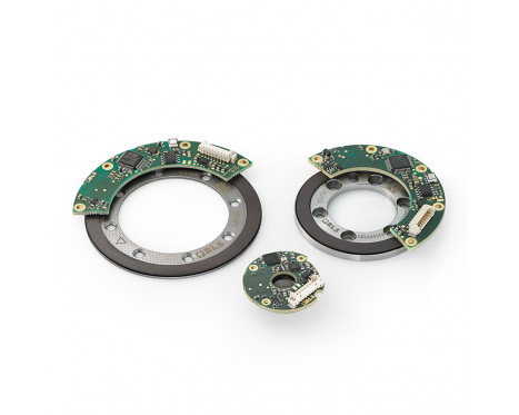
Architecture, materials & specificationsArchitecture options, material requirements and integration constraints
Architecture options
| Approach | Mechanism | Advantages | Trade-offs |
|---|---|---|---|
| Optical | A detector reads a patterned scale. | Supports fine position measurement without a magnetic target. | Scale cleanliness, alignment and protection affect installed accuracy. |
| Magnetic | Sensors read the field from a magnetic target. | Works without a clear optical path. | Target alignment and stray fields from nearby motors affect measurement. |
| Inductive | Conductive patterns couple electromagnetic signals across a gap. | Can use compact PCB-based sensing without a permanent-magnet target. | Target geometry, spacing and electronics determine accuracy. |
| Capacitive | Patterned electrodes sense position through electric-field coupling. | Offers another compact option without an optical scale or magnetic target. | Installation tolerances and the sensing electronics still constrain performance. |
Specifications & operating limits
Resolution is the smallest reported position step. Accuracy is closeness to the true position; repeatability is how consistently the same position is reported. More bits can give finer steps without improving installed accuracy.
Materials & constraints
- Scale or target
- Glass, metal or magnetic material depends on the sensing method.
- Electronics
- Photodetectors or sensing circuits convert position into a signal.
- PCB conductors
- Form sensing patterns in inductive designs.
Dependencies & engineering limits
- Mounting & accuracy
- An off-centre scale, tilted mounting or moving bearing axis adds position error. These installation errors affect accuracy independently of resolution. Bearings
- Assembly & verification
- Installed alignment and signal quality can vary across the motion range. Calibrating predictable error can improve results, but it does not remove looseness or changing deformation.
- Timing & control response
- The controller needs the correct interface and timely readings. Transmission delay and inconsistent timing affect the feedback loop even when the measured position is accurate. Compute & control
- Sensor location & what is known
- A motor-side encoder measures before the gearbox; an output-side encoder measures after it. Transmission play and twist can make those positions differ under load. Strain-wave / harmonic reducers
Manufacturing & assembly
Parts & processes
No matching parts or examples.
Representative industrial route. Scale manufacture supplies the precision position reference. An illuminated readhead and decoding electronics join it to form an optical encoder; magnetic sensing uses a different target and readhead.
Scale
Other routes
Manufacturing · Representative route. Scale manufacture and readhead installation lead to measurement of the completed axis.
Related parts & processes 4
Functional chain · Representative route. A patterned scale is read optically and decoded into position.
Related parts & processes 2
Assembly · Representative route. AksIM-2 provides the reference assembly.
Related parts & processes 2
Assembly · Representative route. Separate inputs converge into the supplied component.
Related parts & processes 3
Glass or metal carries a precisely positioned optical pattern. The scale geometry encodes linear or rotary movement.
Production step for Patterned scale: Graduation & patterning.
Measurement or signal input to Optical readhead: Patterned scale.
Assembly input to Readhead alignment: Patterned scale.
Assembly input to Optical encoder: Patterned scale.
This step
Related references
Patterned scale
Glass or metal carries a precisely positioned optical pattern. The scale geometry encodes linear or rotary movement.
Scale accuracy and mounting accuracy both matter.
Inputs & supporting parts
Scribing or etching forms the scale markings.
Where this fits
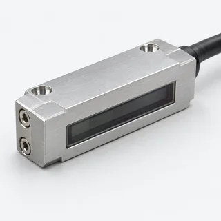
Illumination and a photodetector read the scale without mechanical contact.
A rigid bracket fixes the readhead’s clearance and orientation to the scale.
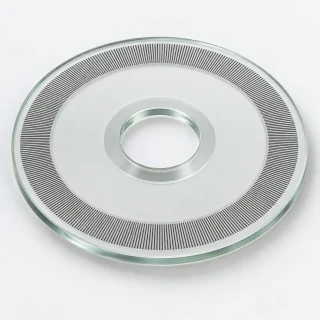
A patterned scale, illuminated readhead and decoding electronics form the optical encoder.
Sources & technical scope
Illustrative images of generic materials and components.
This step
Related references
Illumination and a photodetector read the scale without mechanical contact.
Measurement or signal input to Optical readhead: Patterned scale.
Measurement or signal input to Signal decoding: Optical readhead.
Assembly input to Readhead alignment: Optical readhead.
Assembly input to Optical encoder: Optical readhead.
This step
Related references
Optical readhead
Illumination and a photodetector read the scale without mechanical contact.
Contamination, alignment and readhead clearance affect the signal.
Inputs & supporting parts
Glass or metal carries a precisely positioned optical pattern.
Where this fits
Electronics decode absolute position or incremental changes and transmit them to the controller.
A rigid bracket fixes the readhead’s clearance and orientation to the scale.
A patterned scale, illuminated readhead and decoding electronics form the optical encoder.
Sources & technical scope
Illustrative images of generic materials and components.
This step
Related references
A magnetised target provides a changing magnetic field as it moves relative to the sensor.
Assembly input to Magnetic-ring retention: Magnetic target.
Magnetic target
A magnetised target provides a changing magnetic field as it moves relative to the sensor.
The magnetic route is an alternative to an optical scale.
Where this fits
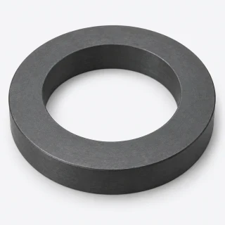
AksIM rings use fasteners, press fits or adhesive, depending on ring type.
Examples from industry 1
GenericAksIM-2 uses a compact readhead and an axially magnetised ring. RLS documents ring sizes, interface variants and a self-calibration option.
Sources & technical scope
Illustrative images of generic materials and components.
This step
Link to this detailA magnetic sensing element converts field changes into a position signal.
Design alternative for Magnetic readhead: On-axis angle-sensor IC.
Assembly input to Magnetic readhead: Magnetic-ring retention.
Checks on Magnetic readhead: Readhead setup & self-calibration.
Magnetic readhead
A magnetic sensing element converts field changes into a position signal.
Target geometry and installation are part of the measurement system.
Inputs & supporting parts
An on-axis magnetic encoder can use a sensor IC on a circuit board beside a rotating magnet.
AksIM rings use fasteners, press fits or adhesive, depending on ring type.
Where this fits
The AksIM-2 readhead reads an axially magnetised ring.
Sources & technical scope
Illustrative images of generic materials and components.
This step
Related references
Electronics decode absolute position or incremental changes and transmit them to the controller.
Measurement or signal input to Signal decoding: Optical readhead.
Supporting dependency for Signal decoding: Interpolation error.
Measurement or signal input to Installed position: Signal decoding.
Assembly input to Optical encoder: Signal decoding.
Signal decoding
Electronics decode absolute position or incremental changes and transmit them to the controller.
Absolute versus incremental is a separate choice from sensing technology.
Inputs & supporting parts
Illumination and a photodetector read the scale without mechanical contact.
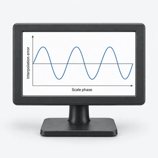
Readhead electronics subdivide the scale pitch.
Where this fits
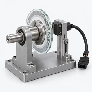
The reported position refers to the axis and location where the encoder is mounted.
A patterned scale, illuminated readhead and decoding electronics form the optical encoder.
Sources & technical scope
Illustrative images of generic materials and components.
This step
Related references
The reported position refers to the axis and location where the encoder is mounted.
Measurement or signal input to Installed position: Signal decoding.
Supporting dependency for Installed position: Bearing & mounting.
Supporting dependency for Installed position: Repeatable-error compensation.
Measurement or signal input to Installed position: Readhead setup & self-calibration.
Checks on Installed position: Alignment check.
Installed position
The reported position refers to the axis and location where the encoder is mounted.
An output-side encoder measures position after the gearbox, including its deflection.
Inputs & supporting parts
Electronics decode absolute position or incremental changes and transmit them to the controller.
Eccentricity, tilt and bearing motion add installed error.
An error map can correct repeatable installed errors; opposed readheads offer another compensation method.
The AksIM-2 readhead reads an axially magnetised ring.
Where this fits
Alignment and accuracy checks cover the installed movement range.
Sources & technical scope
Illustrative images of generic materials and components.
Related references
Eccentricity, tilt and bearing motion add installed error.
Supporting dependency for Installed position: Bearing & mounting.
Supporting dependency for Readhead alignment: Bearing & mounting.
Related references
Bearing & mounting
Bearings →Eccentricity, tilt and bearing motion add installed error.
Where this fits
The reported position refers to the axis and location where the encoder is mounted.
A rigid bracket fixes the readhead’s clearance and orientation to the scale.
Sources & technical scope
Illustrative images of generic materials and components.
Related references
Alignment and accuracy checks cover the installed movement range.
Checks on Installed position: Alignment check.
Alignment check
Alignment and accuracy checks cover the installed movement range.
Inputs & supporting parts
The reported position refers to the axis and location where the encoder is mounted.
Sources & technical scope
Illustrative images of generic materials and components.
Link to this detailAn on-axis magnetic encoder can use a sensor IC on a circuit board beside a rotating magnet.
Design alternative for Magnetic readhead: On-axis angle-sensor IC.
This step
Related references
On-axis angle-sensor IC
An on-axis magnetic encoder can use a sensor IC on a circuit board beside a rotating magnet.
The magnet arrangement differs from an off-axis encoder ring.
Where this fits
A magnetic sensing element converts field changes into a position signal.
Examples from industry 1
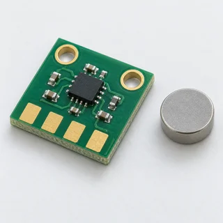 Generic
AS5047P is an on-axis magnetic angle-sensor IC with absolute SPI readout and incremental outputs.
Sources & technical scope
Illustrative images of generic materials and components.
This step
Related references
AksIM-2 uses a compact readhead and an axially magnetised ring. RLS documents ring sizes, interface variants and a self-calibration option.
Related references
RLS · AksIM-2
Manufacturer offeringAksIM-2 uses a compact readhead and an axially magnetised ring. RLS documents ring sizes, interface variants and a self-calibration option.
Ring geometry, readhead spacing and interface configuration determine the assembled encoder’s operation.
Where this fits
A magnetised target provides a changing magnetic field as it moves relative to the sensor.
Sources & technical scope
Illustrative images of generic materials and components.
Related references
AS5047P is an on-axis magnetic angle-sensor IC with absolute SPI readout and incremental outputs.
This step
Infineon · AS5047P
Manufacturer offeringAS5047P is an on-axis magnetic angle-sensor IC with absolute SPI readout and incremental outputs.
Magnet placement, board layout and signal interfaces determine the on-axis integration.
Where this fits
An on-axis magnetic encoder can use a sensor IC on a circuit board beside a rotating magnet.
Sources & technical scope
Illustrative images of generic materials and components.
This step
Link to this detailA glass or metal ring or disc carries the markings that encode angle. Another construction wraps a linear scale around a shaft.
Material input to Graduation & patterning: Scale substrate.
Scale substrate
A glass or metal ring or disc carries the markings that encode angle. Another construction wraps a linear scale around a shaft.
Uneven spacing of the markings introduces angle-measurement error.
Sources & technical scope
Illustrative images of generic materials and components.
Link to this detailScribing or etching forms the scale markings. Their spacing sets the angular reference read by the optical head.
Material input to Graduation & patterning: Scale substrate.
Production step for Patterned scale: Graduation & patterning.
Related references
Graduation & patterning
Scribing or etching forms the scale markings. Their spacing sets the angular reference read by the optical head.
The marking method depends on the scale material and geometry.
Inputs & supporting parts
A glass or metal ring or disc carries the markings that encode angle.
Where this fits
Glass or metal carries a precisely positioned optical pattern.
Sources & technical scope
Illustrative images of generic materials and components.
Related references
Interpolation subdivides a scale pitch into reported positions. Signal nonlinearity creates cyclic position error within that pitch.
Supporting dependency for Signal decoding: Interpolation error.
Related references
Interpolation error
Readhead electronics subdivide the scale pitch. Nonlinearity creates cyclic error within that pitch.
Interpolation accuracy and output resolution are separate specifications.
Where this fits
Electronics decode absolute position or incremental changes and transmit them to the controller.
Sources & technical scope
Illustrative images of generic materials and components.
Related references
Measurement against an angular reference captures scale error together with mounting and axis errors.
Checks on Readhead alignment: Installed error measurement.
Sequence: Readhead alignment → Installed error measurement.
Measurement or signal input to Repeatable-error compensation: Installed error measurement.
Production step for Optical encoder: Installed error measurement.
Related references
Installed error measurement
Comparison with a recognised angular reference measures the encoder’s error after final mounting.
Installed measurement includes errors from mounting and axis motion.
Inputs & supporting parts
A rigid bracket fixes the readhead’s clearance and orientation to the scale.
Where this fits
An error map can correct repeatable installed errors; opposed readheads offer another compensation method.
A patterned scale, illuminated readhead and decoding electronics form the optical encoder.
Sources & technical scope
Illustrative images of generic materials and components.
Related references
An error map can correct repeatable installed errors; opposed readheads offer another compensation method.
Measurement or signal input to Repeatable-error compensation: Installed error measurement.
Supporting dependency for Installed position: Repeatable-error compensation.
Related references
Repeatable-error compensation
An error map can correct repeatable installed errors; opposed readheads offer another compensation method.
Time-varying bearing motion and shaft torsion require separate assessment.
Inputs & supporting parts
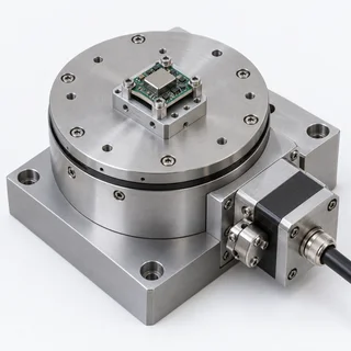
Comparison with a recognised angular reference measures the encoder’s error after final mounting.
Where this fits
The reported position refers to the axis and location where the encoder is mounted.
Sources & technical scope
Illustrative images of generic materials and components.
Related references
A rigid bracket fixes the readhead’s clearance and orientation to the scale. Signal checks over a full revolution reveal alignment problems.
Assembly input to Readhead alignment: Patterned scale.
Assembly input to Readhead alignment: Optical readhead.
Supporting dependency for Readhead alignment: Bearing & mounting.
Checks on Readhead alignment: Installed error measurement.
Sequence: Readhead alignment → Installed error measurement.
Readhead alignment
A rigid bracket fixes the readhead’s clearance and orientation to the scale. Signal checks over a full revolution reveal alignment problems.
Movement of the bracket changes the measured angle.
Inputs & supporting parts
Glass or metal carries a precisely positioned optical pattern.
Illumination and a photodetector read the scale without mechanical contact.
Eccentricity, tilt and bearing motion add installed error.
Where this fits
Comparison with a recognised angular reference measures the encoder’s error after final mounting.
Sources & technical scope
Illustrative images of generic materials and components.
Link to this detailAksIM rings use fasteners, press fits or adhesive, depending on ring type. The shaft seat and assembly tooling keep the ring parallel and concentric.
Assembly input to Magnetic-ring retention: Magnetic target.
Assembly input to Magnetic readhead: Magnetic-ring retention.
Related references
Magnetic-ring retention
AksIM rings use fasteners, press fits or adhesive, depending on ring type. The shaft seat and assembly tooling keep the ring parallel and concentric.
Press-fit tooling loads the supporting ring; mounting tolerances depend on shaft material.
Inputs & supporting parts
A magnetised target provides a changing magnetic field as it moves relative to the sensor.
Where this fits
A magnetic sensing element converts field changes into a position signal.
Sources & technical scope
Illustrative images of generic materials and components.
Related references
The AksIM-2 readhead reads an axially magnetised ring. It supports SSI, BiSS C or serial interfaces and a self-calibration function.
Checks on Magnetic readhead: Readhead setup & self-calibration.
Measurement or signal input to Installed position: Readhead setup & self-calibration.
Readhead setup & self-calibration
The AksIM-2 readhead reads an axially magnetised ring. It supports SSI, BiSS C or serial interfaces and a self-calibration function.
Inputs & supporting parts
A magnetic sensing element converts field changes into a position signal.
Where this fits
The reported position refers to the axis and location where the encoder is mounted.
Sources & technical scope
Illustrative images of generic materials and components.
Link to this detailA patterned scale, illuminated readhead and decoding electronics form the optical encoder. Scale accuracy, readhead alignment and mounting geometry contribute separately to position accuracy.
Production step for Optical encoder: Installed error measurement.
Assembly input to Optical encoder: Patterned scale.
Assembly input to Optical encoder: Optical readhead.
Assembly input to Optical encoder: Signal decoding.
This step
Related references
Optical encoder
A patterned scale, illuminated readhead and decoding electronics form the optical encoder. Scale accuracy, readhead alignment and mounting geometry contribute separately to position accuracy.
Inputs & supporting parts
Comparison with a recognised angular reference measures the encoder’s error after final mounting.
Glass or metal carries a precisely positioned optical pattern.
Illumination and a photodetector read the scale without mechanical contact.
Electronics decode absolute position or incremental changes and transmit them to the controller.
Sources & technical scope
Illustrative images of generic materials and components.
This step
Related references
Market context
RLS · encoders selected for AIDIN joints

AIDIN selected RLS AksIM-2 absolute encoders for each quadruped joint. The selected 20-bit configuration uses SSI and BiSS-C interfaces; a dual-encoder joint was described as a future design.
Renishaw

Renishaw is expanding encoder production and redesigning some existing products around components in short supply. Its magnetic-encoder sales grew with industrial automation and robotics demand, while semiconductor demand drove optical-encoder growth.
Companies
Browse components →RenishawATOM optical encodersRLSSupply connection · Aidin RoboticsHEIDENHAINKCI dual encoders & ECA angle encodersNetzer PrecisionVLX hollow-shaft absolute encoders
Explore documented supply relationships →

Bearings
Supports moving shafts and joints while carrying radial, axial or combined loads. Selection depends on the joint geometry and load case.
Inside a ball bearing
Watch the rolling elements move between the rings. Use the cutaway to see the raceways, or separate the parts to inspect the assembly.
Drag to rotate · pinch / scroll to zoom
Loading model…
Rings and rolling elements
Balls carry load between the inner and outer raceways. The cage maintains their spacing.
Explore componentAbout this model
Original Korthos illustrative geometry, not a manufacturer’s product or manufacturing CAD. The outer ring is fixed while the inner ring turns; rolling elements spin and travel around the raceway. Colours and tracers explain orientation and motion. Cutaway sections stay open during rotation. Speeds are illustrative; load, friction, slip and service life are not simulated. Crossed-roller principle (THK).
Model scope & reuseArchitecture, materials & specificationsArchitecture options, material requirements and integration constraints
Architecture options
Thin-section bearings have a small ring cross-section. Their rolling-element arrangement determines the loads they support.
| Approach | Mechanism | Advantages | Trade-offs |
|---|---|---|---|
| Crossed rollers | Alternating roller directions carry radial, axial and tilting loads. | Supports combined joint loads in one compact bearing. | Mounting stiffness, alignment and preload strongly affect performance. |
| Paired angular contact | Two angled contact paths support loads in opposing directions. | Bearing spacing can provide strong resistance to joint tilting. | The pair needs space and controlled preload; excess preload raises friction. |
| Thin-section rings | A small ring cross-section leaves a large opening inside the bearing. | Makes room for motors, shafts and cable routing. | Housing support and ring deformation affect performance; load capacity depends on the internal arrangement. |
Specifications & operating limits
Radial loads act across the shaft; axial loads act along it; moment loads try to tilt it. Static ratings address permanent deformation under load. Dynamic ratings support fatigue-life calculations under defined loads and operating conditions.
Materials & constraints
- Hardened bearing steels
- Hardened rings and rolling elements carry repeated contact stress. Alloy, heat treatment, surface finish and protection from moisture and contamination affect fatigue and wear.
- Silicon nitride in hybrid bearings
- Hybrid designs combine ceramic rolling elements with steel rings. Silicon nitride provides electrical insulation and lower rolling-element mass. Its contact behaviour and cost differ from steel.
- Steel, brass or polymer cages
- The cage spaces the rolling elements. Material choice depends on speed, temperature, lubricant and loading; a lightweight polymer cage still needs adequate stiffness and chemical compatibility.
- Seals & grease
- Seals help keep dirt out but can add friction. Base-oil viscosity, grease consistency, temperature capability and replenishment influence life, particularly where a joint repeatedly moves through a small angle.
Dependencies & engineering limits
- Housing & bearing fit
- The bearing seat supports and locates the ring; distortion changes its internal contact conditions. Aluminium housings and steel rings expand differently as they heat, so the installed fit can change. Housing stiffness, operating temperatures and retention affect alignment and wear alongside the bearing’s catalogue load rating. Structure & materials
- Manufacturing & preload
- Raceway finish, geometry and controlled fits affect contact conditions. Preload removes clearance but excessive internal loading raises friction and reduces life.
- Small movements & wear
- Repeated short movements can make lubrication more difficult than continuous rotation. The joint cycle, lubricant and contamination conditions therefore affect wear alongside speed and load.
- Wear & positioning error
- Bearing movement can shift the axis seen by an encoder and the attached limb. Mechanical movement adds position error independently of the encoder’s resolution. Encoders & position sensors
Manufacturing & assembly
Parts & processes
No matching parts or examples.
Representative industrial route. This flow follows a ball bearing: rings, balls and cages are made separately, then assembled. Raceway finish, geometry and cleanliness determine how the bearing carries load and turns.
Rings
Balls
Cage
Other routes
Manufacturing · Representative route. Ring manufacture runs alongside ball and cage production; the parts converge at bearing assembly.
Related parts & processes 5
Assembly · Representative route. Rings and rolling elements are assembled into a bearing arrangement.
Related parts & processes 4
Manufacturing · Representative route. Ball manufacture feeds the same bearing assembly.
Related parts & processes 3
Manufacturing · Representative route. The backing, porous interlayer and sliding surface form a composite bearing material.
Assembly · Representative route. Finished rings, rolling elements and cage converge at assembly.
Related parts & processes 6
Assembly · Representative route. Separate inputs converge into the supplied component.
Related parts & processes 4
Inner and outer raceways locate the rolling contacts and transfer loads into the surrounding structure.
Design alternative for Rings & raceways: Through-hardening bearing steel.
Production step for Rings & raceways: Raceway grinding & finishing.
Assembly input to Bearing arrangement: Rings & raceways.
Assembly input to Clean assembly & lubrication: Rings & raceways.
Assembly input to Finished ball bearing: Rings & raceways.
Rings & raceways
Inner and outer raceways locate the rolling contacts and transfer loads into the surrounding structure.
Geometry and surface condition influence the contacts.
Inputs & supporting parts
100Cr6 is a through-hardening steel used for rolling-bearing components.
Grinding establishes ring geometry; fine finishing improves the running surfaces.
Where this fits
The bearing type and arrangement determine how radial, axial and moment loads are supported.
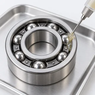
Washed rings, rolling elements and cage are assembled, set and greased.
Rings, balls, cage and lubricant form the illustrated bearing.
Sources & technical scope
Illustrative images of generic materials and components.
This step
Related references
Balls or rollers transmit load between the raceways.
Production step for Rolling elements: Ball grinding & lapping.
Assembly input to Bearing arrangement: Rolling elements.
Assembly input to Clean assembly & lubrication: Rolling elements.
Assembly input to Finished ball bearing: Rolling elements.
Rolling elements
Balls or rollers transmit load between the raceways.
Different contact geometries suit different combinations of load and space.
Inputs & supporting parts
Grinding brings balls toward final size; abrasive lapping between plates refines the spherical surface.
Where this fits
The bearing type and arrangement determine how radial, axial and moment loads are supported.
Washed rings, rolling elements and cage are assembled, set and greased.
Rings, balls, cage and lubricant form the illustrated bearing.
Sources & technical scope
Illustrative images of generic materials and components.
This step
Related references
The bearing type and arrangement determine how radial, axial and moment loads are supported.
Assembly input to Bearing arrangement: Rings & raceways.
Assembly input to Bearing arrangement: Rolling elements.
Supporting dependency for Bearing arrangement: Lubrication & seals.
Supporting dependency for Bearing arrangement: Preload & assembly.
Production step for Bearing arrangement: Clean assembly & lubrication.
Sequence: Final bearing inspection → Bearing arrangement.
Used in Supported joint: Bearing arrangement.
Bearing arrangement
The bearing type and arrangement determine how radial, axial and moment loads are supported.
Catalogue capacity must be assessed in the installed arrangement.
Inputs & supporting parts
Inner and outer raceways locate the rolling contacts and transfer loads into the surrounding structure.
Balls or rollers transmit load between the raceways.
Lubricant and contamination protection affect friction and wear.
Controlled preload can remove clearance.
Washed rings, rolling elements and cage are assembled, set and greased.
After assembly and washing, inspect the completed bearing before marking and packing.
Where this fits
The installed bearing locates moving components under the joint’s actual loads.
Examples from industry 1
GenericTHK offers crossed-roller rings for robot joints and swivelling units. Alternating roller orientations support radial, axial and moment loading within one bearing assembly.
Sources & technical scope
Illustrative images of generic materials and components.
This step
Related references
The installed bearing locates moving components under the joint’s actual loads.
Used in Supported joint: Bearing arrangement.
Supporting dependency for Supported joint: Seats & fits.
Supported joint
Integrated actuators →The installed bearing locates moving components under the joint’s actual loads.
Housing distortion and temperature can change fit.
Inputs & supporting parts
The bearing type and arrangement determine how radial, axial and moment loads are supported.
Housing and shaft seats locate the bearing rings.
Sources & technical scope
Illustrative images of generic materials and components.
This step
Related references
Housing and shaft seats locate the bearing rings.
Supporting dependency for Supported joint: Seats & fits.
Seats & fits
Structure & materials →Housing and shaft seats locate the bearing rings.
Aluminium and steel expand differently; temperature changes installed fit.
Where this fits
The installed bearing locates moving components under the joint’s actual loads.
Sources & technical scope
Illustrative images of generic materials and components.
This step
Link to this detailLubricant and contamination protection affect friction and wear.
Supporting dependency for Bearing arrangement: Lubrication & seals.
Material input to Clean assembly & lubrication: Lubrication & seals.
Assembly input to Finished ball bearing: Lubrication & seals.
Lubrication & seals
Lubricant and contamination protection affect friction and wear.
Repeated small movements have different lubrication conditions from continuous rotation.
Where this fits
The bearing type and arrangement determine how radial, axial and moment loads are supported.
Washed rings, rolling elements and cage are assembled, set and greased.
Rings, balls, cage and lubricant form the illustrated bearing.
Sources & technical scope
Illustrative images of generic materials and components.
This step
Related references
Preload removes bearing clearance and adds internal loading. Its setting affects stiffness, friction and service life.
Supporting dependency for Bearing arrangement: Preload & assembly.
Supporting dependency for Clean assembly & lubrication: Preload & assembly.
Preload & assembly
Controlled preload can remove clearance.
Excess internal loading raises friction and can shorten life.
Where this fits
The bearing type and arrangement determine how radial, axial and moment loads are supported.
Washed rings, rolling elements and cage are assembled, set and greased.
Sources & technical scope
Illustrative images of generic materials and components.
This step
Link to this detail100Cr6 is a through-hardening steel used for rolling-bearing components.
Design alternative for Rings & raceways: Through-hardening bearing steel.
Material input to Ring forming & turning: Through-hardening bearing steel.
Through-hardening bearing steel
100Cr6 is a through-hardening steel used for rolling-bearing components.
Specify the steel grade, heat treatment and finished dimensions together.
Where this fits
Inner and outer raceways locate the rolling contacts and transfer loads into the surrounding structure.
A conventional steel-bearing route forms ring blanks and turns them before heat treatment.
Examples from industry 1
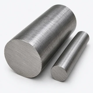 Generic
Ovako lists through-hardening bearing steels, including 100Cr6, for rolling-bearing components and other high-fatigue applications.
Sources & technical scope
Illustrative images of generic materials and components.
Link to this detailOvako lists through-hardening bearing steels, including 100Cr6, for rolling-bearing components and other high-fatigue applications.
Ovako · through-hardening grades
Manufacturer offeringOvako lists through-hardening bearing steels, including 100Cr6, for rolling-bearing components and other high-fatigue applications.
Where this fits
100Cr6 is a through-hardening steel used for rolling-bearing components.
Sources & technical scope
Illustrative images of generic materials and components.
Link to this detailTHK offers crossed-roller rings for robot joints and swivelling units. Alternating roller orientations support radial, axial and moment loading within one bearing assembly.
This step
Related references
THK · Cross-Roller Ring
Manufacturer offeringTHK offers crossed-roller rings for robot joints and swivelling units. Alternating roller orientations support radial, axial and moment loading within one bearing assembly.
Mounting dimensions and preload set the bearing’s installed stiffness and internal loading.
Where this fits
The bearing type and arrangement determine how radial, axial and moment loads are supported.
Sources & technical scope
Illustrative images of generic materials and components.
This step
Related references
A conventional steel-bearing route forms ring blanks and turns them before heat treatment.
Material input to Ring forming & turning: Through-hardening bearing steel.
Sequence: Ring forming & turning → Heat treatment.
Related references
Ring forming & turning
A conventional steel-bearing route forms ring blanks and turns them before heat treatment.
This path follows a conventional ball-bearing ring.
Inputs & supporting parts
100Cr6 is a through-hardening steel used for rolling-bearing components.
Where this fits
Controlled heat treatment gives bearing components their required material condition before precision finishing.
Sources & technical scope
Illustrative images of generic materials and components.
Related references
Controlled heat treatment gives bearing components their required material condition before precision finishing.
Sequence: Ring forming & turning → Heat treatment.
Sequence: Heat treatment → Raceway grinding & finishing.
Heat treatment
Controlled heat treatment gives bearing components their required material condition before precision finishing.
Steel grade and heat treatment determine the resulting hardness and toughness.
Inputs & supporting parts
A conventional steel-bearing route forms ring blanks and turns them before heat treatment.
Where this fits
Grinding establishes ring geometry; fine finishing improves the running surfaces.
Sources & technical scope
Illustrative images of generic materials and components.
Link to this detailGrinding and finishing establish raceway geometry and surface quality after ring forming and heat treatment. These surfaces carry the rolling-contact load.
Sequence: Heat treatment → Raceway grinding & finishing.
Checks on Raceway grinding & finishing: Geometry & defect inspection.
Production step for Rings & raceways: Raceway grinding & finishing.
Raceway grinding & finishing
Grinding establishes ring geometry; fine finishing improves the running surfaces.
Rolling elements are manufactured separately.
Inputs & supporting parts
Controlled heat treatment gives bearing components their required material condition before precision finishing.
Where this fits
Inspection checks ring dimensions, profiles and defects against manufacturing requirements.
Inner and outer raceways locate the rolling contacts and transfer loads into the surrounding structure.
Sources & technical scope
Illustrative images of generic materials and components.
Related references
A cage separates rolling elements in the illustrated ball-bearing assembly.
Production step for Cage or separators: Cage manufacture.
Assembly input to Clean assembly & lubrication: Cage or separators.
Assembly input to Finished ball bearing: Cage or separators.
Cage or separators
A cage separates rolling elements in the illustrated ball-bearing assembly.
Cage, separator and full-complement arrangements vary by bearing design.
Inputs & supporting parts
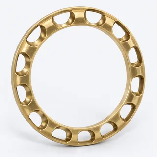
Sheet-steel cages are drawn, polymer cages moulded, and solid metal cages machined.
Where this fits
Washed rings, rolling elements and cage are assembled, set and greased.
Rings, balls, cage and lubricant form the illustrated bearing.
Sources & technical scope
Illustrative images of generic materials and components.
Related references
Inspection checks ring dimensions, profiles and defects against manufacturing requirements.
Checks on Raceway grinding & finishing: Geometry & defect inspection.
Sequence: Geometry & defect inspection → Clean assembly & lubrication.
Geometry & defect inspection
Inspection checks ring dimensions, profiles and defects against manufacturing requirements.
Inputs & supporting parts
Grinding establishes ring geometry; fine finishing improves the running surfaces.
Where this fits
Washed rings, rolling elements and cage are assembled, set and greased.
Sources & technical scope
Illustrative images of generic materials and components.
Related references
Wire is cut into slugs for cold heading into ball blanks. The ball route runs alongside ring and cage manufacture.
Material input to Cold heading & heat treatment: Bearing-ball wire.
Bearing-ball wire
Wire is cut into slugs for cold heading into ball blanks. The ball route runs alongside ring and cage manufacture.
Where this fits
Cold heading forms the ball blank.
Sources & technical scope
Illustrative images of generic materials and components.
Link to this detailCold heading forms the ball blank. Heat treatment establishes hardness before grinding and lapping.
Material input to Cold heading & heat treatment: Bearing-ball wire.
Sequence: Cold heading & heat treatment → Ball grinding & lapping.
Cold heading & heat treatment
Cold heading forms the ball blank. Heat treatment establishes hardness before grinding and lapping.
Inputs & supporting parts
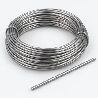
Wire is cut into slugs for cold heading into ball blanks.
Where this fits
Grinding brings balls toward final size; abrasive lapping between plates refines the spherical surface.
Sources & technical scope
Illustrative images of generic materials and components.
Link to this detailGrinding brings balls toward final size; abrasive lapping between plates refines the spherical surface.
Sequence: Cold heading & heat treatment → Ball grinding & lapping.
Production step for Rolling elements: Ball grinding & lapping.
Related references
Ball grinding & lapping
Grinding brings balls toward final size; abrasive lapping between plates refines the spherical surface.
Inputs & supporting parts
Cold heading forms the ball blank.
Where this fits
Balls or rollers transmit load between the raceways.
Sources & technical scope
Illustrative images of generic materials and components.
Related references
Sheet-steel cages are drawn, polymer cages moulded, and solid metal cages machined. The pockets separate and guide the rolling elements.
Material input to Cage manufacture: Cage material.
Production step for Cage or separators: Cage manufacture.
Related references
Cage manufacture
Sheet-steel cages are drawn, polymer cages moulded, and solid metal cages machined. The pockets separate and guide the rolling elements.
Inputs & supporting parts
Sheet steel, machinable metal or moulding polymer supplies the cage, depending on bearing design.
Where this fits
A cage separates rolling elements in the illustrated ball-bearing assembly.
Sources & technical scope
Illustrative images of generic materials and components.
Related references
Washed rings, rolling elements and cage are assembled, set and greased. Dimensional and defect checks precede final marking and packing.
Sequence: Geometry & defect inspection → Clean assembly & lubrication.
Assembly input to Clean assembly & lubrication: Rolling elements.
Assembly input to Clean assembly & lubrication: Rings & raceways.
Assembly input to Clean assembly & lubrication: Cage or separators.
Material input to Clean assembly & lubrication: Lubrication & seals.
Supporting dependency for Clean assembly & lubrication: Preload & assembly.
Production step for Bearing arrangement: Clean assembly & lubrication.
Sequence: Clean assembly & lubrication → Final bearing inspection.
Related references
NSK · manufacturing and inspection methods (aerospace example)SKF: rolling bearing selectionNTN · rolling bearing manufacture, section 2.3SKF: wear and surface fatigueRenishaw: installed rotary-encoder accuracySKF: aluminium housings and bearing fits (pp. 42, 70)NTN-SNR · rings, balls and cage production
Clean assembly & lubrication
Washed rings, rolling elements and cage are assembled, set and greased. Dimensional and defect checks precede final marking and packing.
Inputs & supporting parts
Inspection checks ring dimensions, profiles and defects against manufacturing requirements.
Balls or rollers transmit load between the raceways.
Inner and outer raceways locate the rolling contacts and transfer loads into the surrounding structure.
A cage separates rolling elements in the illustrated ball-bearing assembly.
Lubricant and contamination protection affect friction and wear.
Controlled preload can remove clearance.
Where this fits
The bearing type and arrangement determine how radial, axial and moment loads are supported.
After assembly and washing, inspect the completed bearing before marking and packing.
Sources & technical scope
Illustrative images of generic materials and components.
Related references
NSK · manufacturing and inspection methods (aerospace example)SKF: rolling bearing selectionNTN · rolling bearing manufacture, section 2.3SKF: wear and surface fatigueRenishaw: installed rotary-encoder accuracySKF: aluminium housings and bearing fits (pp. 42, 70)NTN-SNR · rings, balls and cage production
Steel or bronze backing carries load and supports the sliding-bearing material.
Sequence: Plain-bearing metal backing → Porous bronze interlayer.
Plain-bearing metal backing
Steel or bronze backing carries load and supports the sliding-bearing material.
Sources & technical scope
Illustrative images of generic materials and components.
Link to this detailA sintered bronze layer bonds to the backing and supports the low-friction lining.
Sequence: Plain-bearing metal backing → Porous bronze interlayer.
Sequence: Porous bronze interlayer → Polymer sliding layer.
Porous bronze interlayer
A sintered bronze layer bonds to the backing and supports the low-friction lining.
Sources & technical scope
Illustrative images of generic materials and components.
Link to this detailPTFE or another specified thermoplastic fills the porous layer and forms the running surface. Material grades serve dry or lubricated conditions.
Sequence: Porous bronze interlayer → Polymer sliding layer.
Sequence: Polymer sliding layer → Metal–polymer plain bearing.
Polymer sliding layer
PTFE or another specified thermoplastic fills the porous layer and forms the running surface. Material grades serve dry or lubricated conditions.
Inputs & supporting parts
A sintered bronze layer bonds to the backing and supports the low-friction lining.
Where this fits
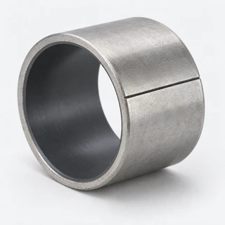
A shaft slides against the polymer lining.
Sources & technical scope
Illustrative images of generic materials and components.
Link to this detailA shaft slides against the polymer lining. Bushes, flanged bushes and thrust washers use this layered material without rolling elements.
Sequence: Polymer sliding layer → Metal–polymer plain bearing.
Metal–polymer plain bearing
A shaft slides against the polymer lining. Bushes, flanged bushes and thrust washers use this layered material without rolling elements.
Sources & technical scope
Illustrative images of generic materials and components.
Link to this detailAfter assembly and washing, inspect the completed bearing before marking and packing. Lubrication and seals follow the specified bearing configuration.
Sequence: Clean assembly & lubrication → Final bearing inspection.
Sequence: Final bearing inspection → Bearing arrangement.
Production step for Finished ball bearing: Final bearing inspection.
Final bearing inspection
After assembly and washing, inspect the completed bearing before marking and packing. Lubrication and seals follow the specified bearing configuration.
Inputs & supporting parts
Washed rings, rolling elements and cage are assembled, set and greased.
Where this fits
The bearing type and arrangement determine how radial, axial and moment loads are supported.
Rings, balls, cage and lubricant form the illustrated bearing.
Sources & technical scope
Illustrative images of generic materials and components.
Link to this detailSheet steel, machinable metal or moulding polymer supplies the cage, depending on bearing design. These are alternative manufacturing routes.
Material input to Cage manufacture: Cage material.
Cage material
Sheet steel, machinable metal or moulding polymer supplies the cage, depending on bearing design. These are alternative manufacturing routes.
Where this fits
Sheet-steel cages are drawn, polymer cages moulded, and solid metal cages machined.
Sources & technical scope
Illustrative images of generic materials and components.
Link to this detailRings, balls, cage and lubricant form the illustrated bearing. Seals or shields depend on the supplied configuration; housing and shaft fits belong to the downstream assembly.
Production step for Finished ball bearing: Final bearing inspection.
Assembly input to Finished ball bearing: Rings & raceways.
Assembly input to Finished ball bearing: Rolling elements.
Assembly input to Finished ball bearing: Cage or separators.
Assembly input to Finished ball bearing: Lubrication & seals.
Finished ball bearing
Rings, balls, cage and lubricant form the illustrated bearing. Seals or shields depend on the supplied configuration; housing and shaft fits belong to the downstream assembly.
Inputs & supporting parts
After assembly and washing, inspect the completed bearing before marking and packing.
Inner and outer raceways locate the rolling contacts and transfer loads into the surrounding structure.
Balls or rollers transmit load between the raceways.
A cage separates rolling elements in the illustrated ball-bearing assembly.
Lubricant and contamination protection affect friction and wear.
Sources & technical scope
Illustrative images of generic materials and components.
Related references
Production equipment
- SupfinaBearing-raceway finishing machines
Superfinishing machines improve bearing raceway surfaces after grinding. The finish controls friction, lubrication and wear at the rolling contact.
Raceway grinding & finishing →EuropeSources
Joint bearings · finished ring raceways
Supfina · bearing-ring and rolling-element machining
Companies
Browse components →
Force / torque sensors
Measures pushing, pulling and twisting loads at wrists, feet or joints for grasping, balance and controlled contact.
Inside a force/torque sensor
Loads cross a metal flexure. Strain gauges and calibrated electronics resolve forces and torques at the mounting interface.
Drag to rotate · scroll to zoom
Loading model…
Source & model scope
Illustrative strain-gauge architecture. Playback magnifies elastic deflection under cyclic axial load. Web and gauge placement explain the load path; they do not specify a calibrated six-axis transducer. Original Korthos geometry.
ATI · force/torque measurement · Model scope & reuseArchitecture, materials & specificationsArchitecture options, material requirements and integration constraints
Architecture options
Axis count defines the resolved force and torque components. Mounting position defines the measured load path.
| Approach | Mechanism | Advantages | Trade-offs |
|---|---|---|---|
| Single-axis sensing | Measures force or torque along one selected axis. | Direct measurement when one load direction is the control target. | Does not separately resolve the other forces and moments. |
| Six-axis sensing | Calibration separates three force directions and three moments. | Reveals combined contact loads at a wrist or foot. | Cross-axis effects, mounting and calibration influence readings. |
| Joint torque sensing | Measures twisting load through a joint’s output path. | Provides feedback for joint force control. | Does not directly show where an object touches the hand or tool. |
Specifications & operating limits
Force is measured in newtons and torque in newton-metres. A six-axis sensor resolves three forces and three moments. Range is the measurable load; resolution is the smallest distinguishable change. Overload capacity describes the load the sensor can withstand beyond its measuring range.
Materials & constraints
- Stainless steel or aluminium
- The elastic structure deforms slightly under load. Its geometry and alloy determine how much it flexes, influencing sensitivity, stiffness and overload behaviour.
- Silicon or metal-foil strain gauges
- Sensing elements turn tiny deformations into electrical changes. The sensing technology and calibration vary between products.
- Housing & seals
- Protect electronics and the sensing assembly in the intended environment.
Dependencies & engineering limits
- Mounting & measured load
- The sensor measures loads passing through its sensing structure. Mounting forces, tool mass and the tool’s centre of gravity all contribute to the reading. Structure & materials
- Calibration & production testing
- Calibration maps the electrical response to force and torque across the measurement axes. Calibration and checks for cross-axis response add work beyond making the metal sensing body.
- Overload & drift
- A collision can exceed the measurement range or damage the sensor. Temperature changes shift readings; permanent deformation or gauge damage can change the calibration.
- Filtering & contact response
- Filtering can make readings quieter but adds delay. The useful feedback rate includes sensor sampling, filtering and communication delay. Compute & control
Manufacturing & assembly
Parts & processes
No matching parts or examples.
Representative industrial route. A strain-gauge sensor joins a machined elastic body with bonded gauges and electronics. Calibration links measured strain to forces and torques.
Body
Assembly inputs
Assembly · Representative route. The elastic body, bonded gauges, leads and protective covering form the sensing assembly.
Related parts & processes 3
Functional chain · Representative route. Mechanical load becomes a calibrated multi-axis measurement.
Related parts & processes 2
Manufacturing · Representative route. A published 17-4PH sensor design demonstrates the machining route.
Related parts & processes 2
Integration / calibration · Representative route. Connect a matched transducer and interface, then apply its calibration.
Related parts & processes 2
Assembly · Representative route. Separate inputs converge into the supplied component.
Related parts & processes 6
A sensing body deforms slightly as mechanical load passes through it.
Supporting dependency for Elastic structure: Mounting & tool mass.
Supporting dependency for Elastic structure: Overload protection.
Design alternative for Elastic structure: Miniature elastic body.
Measurement or signal input to Strain gauges: Elastic structure.
Sequence: Elastic structure → Degreasing, abrasion & cleaning.
Assembly input to Calibrated force–torque sensor: Elastic structure.
Elastic structure
A sensing body deforms slightly as mechanical load passes through it.
Mounting and tool loads contribute to the measurement.
Inputs & supporting parts
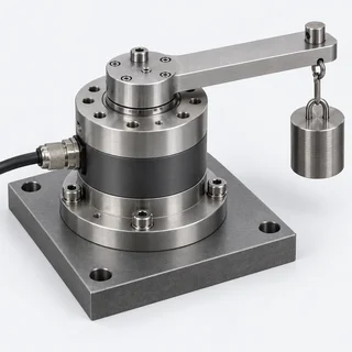
The sensor must be installed in the intended load path.
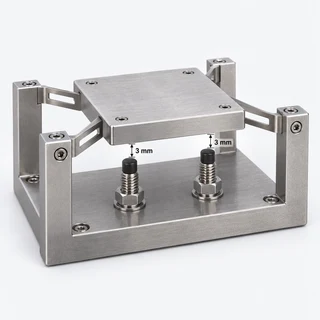
Collisions can exceed the measurement range or damage the sensing structure.
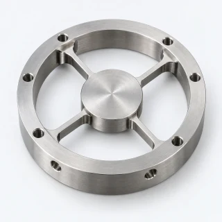
The machined body carries the bonded gauges.
Where this fits
Bonded gauges convert the structure’s deformation into electrical changes.
Degreasing, abrasion and cleaning prepare the elastic body for gauge bonding.
The gauged elastic body, electrical leads, protective layer and readout electronics form a calibrated sensor system.
Sources & technical scope
Illustrative images of generic materials and components.
Related references
Bonded gauges convert the structure’s deformation into electrical changes.
Measurement or signal input to Strain gauges: Elastic structure.
Measurement or signal input to Signal conditioning: Strain gauges.
Assembly input to Gauge positioning & adhesive cure: Strain gauges.
Assembly input to Calibrated force–torque sensor: Strain gauges.
Strain gauges
Bonded gauges convert the structure’s deformation into electrical changes.
Inputs & supporting parts
A sensing body deforms slightly as mechanical load passes through it.
Where this fits
The small electrical signals are conditioned and digitised for force and torque calculation.
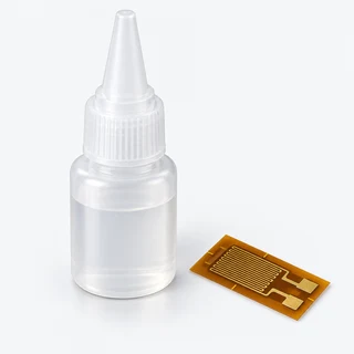
Foil gauges and adhesive become a bonded sensing layer on the elastic body.
The gauged elastic body, electrical leads, protective layer and readout electronics form a calibrated sensor system.
Examples from industry 1
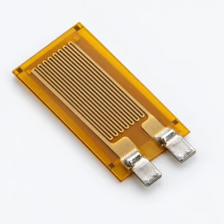 Generic
HBK supplies strain gauges for manufacturers of force, torque, weight and pressure transducers. Its A series combines foil measuring grids with a carrier material in different geometries.
Sources & technical scope
Illustrative images of generic materials and components.
Related references
The small electrical signals are conditioned and digitised for force and torque calculation.
Measurement or signal input to Signal conditioning: Strain gauges.
Design alternative for Signal conditioning: Bridge-signal amplification & ADC.
Assembly input to Signal conditioning: Protective covering.
Measurement or signal input to Multi-axis calibration: Signal conditioning.
Checks on Signal conditioning: Matched sensor & calibration.
Assembly input to Calibrated force–torque sensor: Signal conditioning.
This step
Signal conditioning
The small electrical signals are conditioned and digitised for force and torque calculation.
Noise and filtering affect usable response.
Inputs & supporting parts
Bonded gauges convert the structure’s deformation into electrical changes.
A precision ADC with a programmable-gain amplifier can digitise strain-gauge bridge signals.
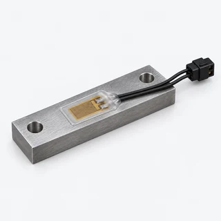
A protective layer seals the gauge and cable entry against moisture.
Where this fits
Calibration maps the sensor signals to forces and moments across the measurement axes.
ATI calibrates the sensor and interface as a matched set with its own calibration data.
The gauged elastic body, electrical leads, protective layer and readout electronics form a calibrated sensor system.
Sources & technical scope
Illustrative images of generic materials and components.
This step
Related references
Calibration maps the sensor signals to forces and moments across the measurement axes.
Measurement or signal input to Multi-axis calibration: Signal conditioning.
Measurement or signal input to Force & torque data: Multi-axis calibration.
Supporting dependency for Calibration matrix: Multi-axis calibration.
Multi-axis calibration
Calibration maps the sensor signals to forces and moments across the measurement axes.
Cross-axis response and temperature influence the installed result.
Inputs & supporting parts
The small electrical signals are conditioned and digitised for force and torque calculation.
Where this fits
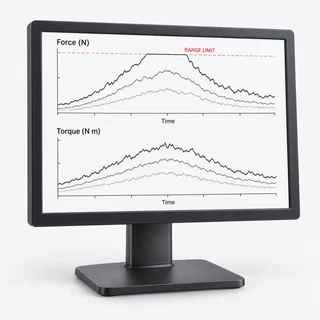
The controller receives the calibrated load measurement at the sensor location.
ATI DAQ systems combine all six gauge outputs through a calibration matrix to obtain forces and torques.
Sources & technical scope
Illustrative images of generic materials and components.
This step
Related references
The controller receives the calibrated load measurement at the sensor location.
Measurement or signal input to Force & torque data: Multi-axis calibration.
Measurement or signal input to Force & torque data: Calibration matrix.
Checks on Force & torque data: Saturation monitoring.
Force & torque data
Compute & control →The controller receives the calibrated load measurement at the sensor location.
Robot safety limits require a system-level assessment of loads and collision cases.
Inputs & supporting parts
Calibration maps the sensor signals to forces and moments across the measurement axes.
ATI DAQ systems combine all six gauge outputs through a calibration matrix to obtain forces and torques.
Where this fits
An overloaded or saturated measurement chain can invalidate the reported force and torque values.
Sources & technical scope
Illustrative images of generic materials and components.
Related references
The sensor must be installed in the intended load path.
Supporting dependency for Elastic structure: Mounting & tool mass.
Mounting & tool mass
Structure & materials →The sensor must be installed in the intended load path.
Tool mass and centre of gravity influence the measured wrench.
Where this fits
A sensing body deforms slightly as mechanical load passes through it.
Sources & technical scope
Illustrative images of generic materials and components.
This step
Related references
Collisions can exceed the measurement range or damage the sensing structure.
Supporting dependency for Elastic structure: Overload protection.
Overload protection
Collisions can exceed the measurement range or damage the sensing structure.
An overload can permanently deform the body or change its calibration.
Where this fits
A sensing body deforms slightly as mechanical load passes through it.
Sources & technical scope
Illustrative images of generic materials and components.
This step
Related references
A precision ADC with a programmable-gain amplifier can digitise strain-gauge bridge signals.
Design alternative for Signal conditioning: Bridge-signal amplification & ADC.
Bridge-signal amplification & ADC
A precision ADC with a programmable-gain amplifier can digitise strain-gauge bridge signals.
Filtering, settling and channel sequencing affect usable response, beyond the converter’s nominal bit count.
Where this fits
The small electrical signals are conditioned and digitised for force and torque calculation.
Examples from industry 1
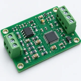 Generic
TI lists strain-gauge sensors among the applications for ADS1262, an ADC with an integrated programmable-gain amplifier and reference.
Sources & technical scope
Illustrative images of generic materials and components.
Related references
HBK supplies strain gauges for manufacturers of force, torque, weight and pressure transducers. Its A series combines foil measuring grids with a carrier material in different geometries.
Related references
HBK · transducer strain gauges
Manufacturer offeringHBK supplies strain gauges for manufacturers of force, torque, weight and pressure transducers. Its A series combines foil measuring grids with a carrier material in different geometries.
The transducer combines gauges, a sensing body, electronics and calibration.
Where this fits
Bonded gauges convert the structure’s deformation into electrical changes.
Sources & technical scope
Illustrative images of generic materials and components.
Related references
TI lists strain-gauge sensors among the applications for ADS1262, an ADC with an integrated programmable-gain amplifier and reference.
Texas Instruments · ADS1262
Manufacturer offeringTI lists strain-gauge sensors among the applications for ADS1262, an ADC with an integrated programmable-gain amplifier and reference.
Channel sequencing, settling time, filtering and calibration affect the usable measurement rate.
Where this fits
A precision ADC with a programmable-gain amplifier can digitise strain-gauge bridge signals.
Sources & technical scope
Illustrative images of generic materials and components.
Link to this detailDegreasing, abrasion and cleaning prepare the elastic body for gauge bonding. Surface condition affects the adhesive bond and measurement stability.
Sequence: Elastic structure → Degreasing, abrasion & cleaning.
Sequence: Miniature elastic body → Degreasing, abrasion & cleaning.
Sequence: Degreasing, abrasion & cleaning → Gauge positioning & adhesive cure.
Degreasing, abrasion & cleaning
Degreasing, abrasion and cleaning prepare the elastic body for gauge bonding. Surface condition affects the adhesive bond and measurement stability.
Inputs & supporting parts
A sensing body deforms slightly as mechanical load passes through it.
The machined body carries the bonded gauges.
Where this fits
Foil gauges and adhesive become a bonded sensing layer on the elastic body.
Sources & technical scope
Illustrative images of generic materials and components.
Related references
The adhesive transfers strain between the elastic body and foil gauge. Bonding chemistry depends on the substrate and operating environment.
Material input to Gauge positioning & adhesive cure: Gauge adhesive.
Assembly input to Calibrated force–torque sensor: Gauge adhesive.
Gauge adhesive
The adhesive transfers strain between the elastic body and foil gauge. Bonding chemistry depends on the substrate and operating environment.
Where this fits
Foil gauges and adhesive become a bonded sensing layer on the elastic body.
The gauged elastic body, electrical leads, protective layer and readout electronics form a calibrated sensor system.
Sources & technical scope
Illustrative images of generic materials and components.
Related references
The adhesive bond transfers surface deformation to the strain gauge. Surface preparation and installation affect strain transfer and measurement accuracy.
Sequence: Degreasing, abrasion & cleaning → Gauge positioning & adhesive cure.
Material input to Gauge positioning & adhesive cure: Gauge adhesive.
Assembly input to Gauge positioning & adhesive cure: Strain gauges.
Assembly input to Terminals & flexible leads: Gauge positioning & adhesive cure.
Gauge positioning & adhesive cure
Foil gauges and adhesive become a bonded sensing layer on the elastic body. Grid orientation and adhesive cure affect strain transfer.
Inputs & supporting parts
Degreasing, abrasion and cleaning prepare the elastic body for gauge bonding.
The adhesive transfers strain between the elastic body and foil gauge.
Bonded gauges convert the structure’s deformation into electrical changes.
Where this fits
Terminals connect fine gauge leads to the measurement cable.
Sources & technical scope
Illustrative images of generic materials and components.
Related references
Each gauge responds to deformation of the loaded structure. A calibration matrix combines the channels into forces and torques.
Supporting dependency for Calibration matrix: Matched sensor & calibration.
Supporting dependency for Calibration matrix: Multi-axis calibration.
Measurement or signal input to Force & torque data: Calibration matrix.
Supporting dependency for Calibrated force–torque sensor: Calibration matrix.
Calibration matrix
ATI DAQ systems combine all six gauge outputs through a calibration matrix to obtain forces and torques.
Each force or torque value combines responses from multiple gauge channels.
Inputs & supporting parts
ATI calibrates the sensor and interface as a matched set with its own calibration data.
Calibration maps the sensor signals to forces and moments across the measurement axes.
Where this fits
The controller receives the calibrated load measurement at the sensor location.
The gauged elastic body, electrical leads, protective layer and readout electronics form a calibrated sensor system.
Sources & technical scope
Illustrative images of generic materials and components.
Related references
ATI calibrates the sensor and interface as a matched set with its own calibration data.
Checks on Signal conditioning: Matched sensor & calibration.
Sequence: Protective covering → Matched sensor & calibration.
Supporting dependency for Calibration matrix: Matched sensor & calibration.
Production step for Calibrated force–torque sensor: Matched sensor & calibration.
Matched sensor & calibration
ATI calibrates the sensor and interface as a matched set with its own calibration data.
Changing a matched component changes the calibration requirements.
Inputs & supporting parts
The small electrical signals are conditioned and digitised for force and torque calculation.
A protective layer seals the gauge and cable entry against moisture.
Where this fits
ATI DAQ systems combine all six gauge outputs through a calibration matrix to obtain forces and torques.
The gauged elastic body, electrical leads, protective layer and readout electronics form a calibrated sensor system.
Sources & technical scope
Illustrative images of generic materials and components.
Related references
An overloaded or saturated measurement chain can invalidate the reported force and torque values.
Checks on Force & torque data: Saturation monitoring.
Related references
Saturation monitoring
An overloaded or saturated measurement chain can invalidate the reported force and torque values.
Calibration range and mechanical overload capacity are different limits.
Inputs & supporting parts
The controller receives the calibrated load measurement at the sensor location.
Sources & technical scope
Illustrative images of generic materials and components.
Related references
Terminals connect fine gauge leads to the measurement cable. Flexible stranded leads and strain relief keep cable motion from pulling on the bond.
Assembly input to Terminals & flexible leads: Gauge positioning & adhesive cure.
Checks on Terminals & flexible leads: Bond & electrical checks.
Assembly input to Calibrated force–torque sensor: Terminals & flexible leads.
Terminals & flexible leads
Terminals connect fine gauge leads to the measurement cable. Flexible stranded leads and strain relief keep cable motion from pulling on the bond.
Inputs & supporting parts
Foil gauges and adhesive become a bonded sensing layer on the elastic body.
Where this fits
Bond inspection, resistance measurement and insulation checks screen the instrumented body before protective covering and calibration.
The gauged elastic body, electrical leads, protective layer and readout electronics form a calibrated sensor system.
Sources & technical scope
Illustrative images of generic materials and components.
Related references
A protective layer seals the gauge and cable entry against moisture. The bond between covering and cable insulation closes the moisture path.
Sequence: Bond & electrical checks → Protective covering.
Assembly input to Signal conditioning: Protective covering.
Sequence: Protective covering → Matched sensor & calibration.
Protective covering
A protective layer seals the gauge and cable entry against moisture. The bond between covering and cable insulation closes the moisture path.
Inputs & supporting parts
Bond inspection, resistance measurement and insulation checks screen the instrumented body before protective covering and calibration.
Where this fits
The small electrical signals are conditioned and digitised for force and torque calculation.
ATI calibrates the sensor and interface as a matched set with its own calibration data.
Sources & technical scope
Illustrative images of generic materials and components.
Related references
Bond inspection, resistance measurement and insulation checks screen the instrumented body before protective covering and calibration.
Checks on Terminals & flexible leads: Bond & electrical checks.
Sequence: Bond & electrical checks → Protective covering.
Related references
Bond & electrical checks
Bond inspection, resistance measurement and insulation checks screen the instrumented body before protective covering and calibration.
Inputs & supporting parts
Terminals connect fine gauge leads to the measurement cable.
Where this fits
A protective layer seals the gauge and cable entry against moisture.
Sources & technical scope
Illustrative images of generic materials and components.
Related references
A published 9.5 mm six-axis sensor uses pretreated 17-4PH stainless bar. Heat treatment precedes precision machining to limit later distortion.
Material input to Wire-EDM flexure machining: Heat-treated stainless stock.
Heat-treated stainless stock
A published 9.5 mm six-axis sensor uses pretreated 17-4PH stainless bar. Heat treatment precedes precision machining to limit later distortion.
Where this fits
In that miniature design, wire electrical-discharge machining creates the gauge-bonding faces and separation slots.
Sources & technical scope
Illustrative images of generic materials and components.
Link to this detailThe sensor body concentrates elastic strain at its gauge sites. Wire EDM can form narrow separation slots and small bonding faces in a heat-treated metal blank.
Material input to Wire-EDM flexure machining: Heat-treated stainless stock.
Production step for Miniature elastic body: Wire-EDM flexure machining.
Wire-EDM flexure machining
In that miniature design, wire electrical-discharge machining creates the gauge-bonding faces and separation slots. Their geometry defines the elastic load path.
Inputs & supporting parts
A published 9.5 mm six-axis sensor uses pretreated 17-4PH stainless bar.
Where this fits
The machined body carries the bonded gauges.
Sources & technical scope
Illustrative images of generic materials and components.
Link to this detailThe machined body carries the bonded gauges. Sandblasting prepares the bonding sites before gauge installation, bridge wiring and final assembly.
Production step for Miniature elastic body: Wire-EDM flexure machining.
Sequence: Miniature elastic body → Degreasing, abrasion & cleaning.
Design alternative for Elastic structure: Miniature elastic body.
Miniature elastic body
The machined body carries the bonded gauges. Sandblasting prepares the bonding sites before gauge installation, bridge wiring and final assembly.
Inputs & supporting parts
In that miniature design, wire electrical-discharge machining creates the gauge-bonding faces and separation slots.
Where this fits
Degreasing, abrasion and cleaning prepare the elastic body for gauge bonding.
A sensing body deforms slightly as mechanical load passes through it.
Sources & technical scope
Illustrative images of generic materials and components.
Related references
The gauged elastic body, electrical leads, protective layer and readout electronics form a calibrated sensor system. Its calibration data maps gauge responses to forces and moments.
Production step for Calibrated force–torque sensor: Matched sensor & calibration.
Assembly input to Calibrated force–torque sensor: Elastic structure.
Assembly input to Calibrated force–torque sensor: Strain gauges.
Assembly input to Calibrated force–torque sensor: Gauge adhesive.
Assembly input to Calibrated force–torque sensor: Terminals & flexible leads.
Assembly input to Calibrated force–torque sensor: Signal conditioning.
Supporting dependency for Calibrated force–torque sensor: Calibration matrix.
Calibrated force–torque sensor
The gauged elastic body, electrical leads, protective layer and readout electronics form a calibrated sensor system. Its calibration data maps gauge responses to forces and moments.
Inputs & supporting parts
ATI calibrates the sensor and interface as a matched set with its own calibration data.
A sensing body deforms slightly as mechanical load passes through it.
Bonded gauges convert the structure’s deformation into electrical changes.
The adhesive transfers strain between the elastic body and foil gauge.
Terminals connect fine gauge leads to the measurement cable.
The small electrical signals are conditioned and digitised for force and torque calculation.
ATI DAQ systems combine all six gauge outputs through a calibration matrix to obtain forces and torques.
Sources & technical scope
Illustrative images of generic materials and components.
Related references
Market context
Force/torque sensor purchasing benchmarks
CHF 3,045MiniONE Gen A · listed price
CHF 4,882.50SensONE Gen A · listed price
CHF 5,407.50Rokubi Gen A · listed price
Examples of retail purchasing costs for different six-axis sensor series. They are not comparable specifications or negotiated OEM prices.
Unitree
Unitree lists foot-end force sensors on Go2 EDU; Air, Pro and X omit them. Dedicated contact sensors therefore enter the component bill through the selected trim.
Companies
Browse components →
IMUs & inertial sensing
Measures body rotation and acceleration. State estimation combines these readings with joint feedback and external observations to track the robot’s motion.
Inside an inertial sensor
A suspended silicon mass responds to acceleration. The enlarged cutaway shows its motion beside the gyroscope, readout and circuit board.
Drag to rotate · scroll to zoom
Loading model…
Source & model scope
Original schematic of a capacitive MEMS accelerometer within an IMU. The single-axis cutaway and amplified motion explain the sensing principle; the board layout is illustrative. Original Korthos geometry.
Analog Devices · MEMS accelerometer principle · Model scope & reuseArchitecture, materials & specificationsArchitecture options, material requirements and integration constraints
Architecture options
| Approach | Mechanism | Advantages | Trade-offs |
|---|---|---|---|
| IMU | Reports acceleration and angular rate. | Fits into the robot’s own state estimator. | Bias and noise accumulate when integrated without other observations. |
| AHRS | Fuses measurements into orientation. | Provides a ready-to-use attitude estimate. | Magnetic heading can be disturbed near motors; filter assumptions affect dynamic behaviour. |
| Visual / LiDAR-inertial | Fuses inertial measurements with observed scene features. | External observations help constrain drift. | Needs calibrated timing and sensor geometry; feature-poor scenes weaken the correction. |
| GNSS-aided INS | Fuses inertial measurements with satellite positioning. | Adds an outdoor position reference. | Satellite visibility limits indoor and obstructed operation. |
Specifications & operating limits
Materials & constraints
- Silicon sensing structures
- MEMS devices use microscopic moving structures formed on silicon. Their motion is converted into electrical measurements.
- Package & circuit board
- A protected sensor package connects to readout, power and interface electronics. Board stress and mounting alignment affect the installed measurement.
- Calibration
- Known motion and temperature tests characterise offsets, sensitivity and axis alignment. Stored corrections compensate these repeatable errors.
Dependencies & engineering limits
- Body motion & joint motion
- An IMU measures the body it is attached to. Joint encoders describe the limbs relative to that body; contact estimates connect the two to the ground. Encoders & position sensors
- Mounting & vibration
- Mount alignment sets the measurement axes. Structural vibration and impact can corrupt readings, while a flexible mount also changes how sensor motion relates to body motion. Structure & materials
- Timing & estimation
- Timestamps place inertial readings alongside camera, joint and contact measurements. Delay or clock mismatch can make otherwise accurate signals describe different moments. Compute & control
- Manufacturing & calibration
- Fabrication, packaging and board assembly establish the sensing hardware. Motion and temperature calibration then characterise each unit’s scale, bias and axis alignment.
- Drift & external references
- Small gyro and acceleration errors accumulate during integration. Vision, LiDAR, contact constraints or GNSS provide additional observations; each has its own operating limits. Cameras / depth vision
Manufacturing & assembly
Parts & processes
No matching parts or examples.
Representative industrial route. Silicon micromachining produces MEMS inertial sensing structures. Packaging, readout and calibration combine three acceleration axes and three angular-rate axes into a six-axis IMU.
MEMS
Manufacturing · Representative route. Bosch process references explain micromachining and cavity sealing.
Related parts & processes 1
Functional chain · Representative route. Acceleration and angular-rate sensors feed a common measurement and calibration chain.
Related parts & processes 3
Integration / calibration · Representative route. ADI calibration methods and a packaged IMU illustrate the integration stages.
Related parts & processes 4
Assembly · Representative route. The sealed sensing structure needs packaging and electronics before calibration.
Related parts & processes 3
Integration / calibration · Representative route. Generic integration stages; the Bosch wafer processes and ADI module are separate technical references.
Related parts & processes 4
Three-axis accelerometers measure specific force.
Used in Accelerometers: Proof mass, springs & electrodes.
Measurement or signal input to Conditioning & readout: Accelerometers.
Accelerometers
Three-axis accelerometers measure specific force.
Gravity contributes to the reading of a stationary sensor.
Inputs & supporting parts
A capacitive accelerometer suspends a proof mass on springs between sensing electrodes.
Where this fits
Readout electronics digitise the inertial measurements.
Sources & technical scope
Illustrative images of generic materials and components.
Related references
Three-axis gyroscopes measure angular rate.
Measurement or signal input to Conditioning & readout: Gyroscopes.
Gyroscopes
Three-axis gyroscopes measure angular rate.
Integrating small errors accumulates drift.
Where this fits
Readout electronics digitise the inertial measurements.
Sources & technical scope
Illustrative images of generic materials and components.
Link to this detailReadout electronics digitise the inertial measurements.
Measurement or signal input to Conditioning & readout: Accelerometers.
Measurement or signal input to Conditioning & readout: Gyroscopes.
Measurement or signal input to Factory calibration: Conditioning & readout.
Used in Packaged IMU & board connection: Conditioning & readout.
Related references
Conditioning & readout
Readout electronics digitise the inertial measurements.
Data-ready and synchronisation interfaces determine measurement timing.
Inputs & supporting parts
Three-axis accelerometers measure specific force.
Three-axis gyroscopes measure angular rate.
Where this fits
Known motion and temperature characterise bias, sensitivity and axis alignment.
ADIS16500 combines three-axis acceleration and angular-rate sensing with calibration and SPI readout in a surface-mount package.
Sources & technical scope
Illustrative images of generic materials and components.
Related references
Known motion and temperature characterise bias, sensitivity and axis alignment.
Measurement or signal input to Factory calibration: Conditioning & readout.
Supporting dependency for Factory calibration: Temperature calibration.
Measurement or signal input to Calibrated IMU: Factory calibration.
Factory calibration
Known motion and temperature characterise bias, sensitivity and axis alignment.
Calibration compensates repeatable errors in the sensor response.
Inputs & supporting parts
Readout electronics digitise the inertial measurements.
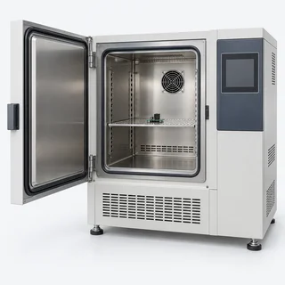
Gyroscope bias and scale factor can be characterised at multiple temperatures for compensation.
Where this fits
An IMU supplies acceleration and angular-rate measurements to the robot.
Sources & technical scope
Illustrative images of generic materials and components.
Related references
An IMU supplies acceleration and angular-rate measurements to the robot.
Measurement or signal input to Calibrated IMU: Factory calibration.
Supporting dependency for Calibrated IMU: Installed alignment.
Design alternative for Calibrated IMU: Six-axis MEMS package.
Used in Calibrated IMU: Packaged IMU & board connection.
Supporting dependency for Calibrated IMU: Sensitivity & axis alignment.
Sequence: Sensitivity & axis alignment → Calibrated IMU.
Measurement or signal input to State estimation: Calibrated IMU.
Calibrated IMU
An IMU supplies acceleration and angular-rate measurements to the robot.
Position estimates accumulate drift when inertial measurements are integrated over time.
Inputs & supporting parts
Known motion and temperature characterise bias, sensitivity and axis alignment.
The sensor axes must be related to the robot’s body frame.
A packaged three-axis accelerometer and three-axis gyroscope supplies six inertial measurement axes.
ADIS16500 combines three-axis acceleration and angular-rate sensing with calibration and SPI readout in a surface-mount package.
ADI’s ADIS16500 factory calibration characterises sensitivity, bias and alignment of the inertial channels.
Where this fits
The robot combines inertial readings with joint and external observations.
Examples from industry 1
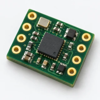 Generic
ADIS16470 combines inertial sensors with signal conditioning and factory calibration for sensitivity, bias and alignment. Analog Devices lists robotics among its applications.
Sources & technical scope
Illustrative images of generic materials and components.
Related references
The sensor axes must be related to the robot’s body frame.
Assembly input to Installed alignment: Packaged IMU & board connection.
Supporting dependency for Calibrated IMU: Installed alignment.
Installed alignment
Structure & materials →The sensor axes must be related to the robot’s body frame.
Mounting error changes how measured motion is interpreted.
Inputs & supporting parts
ADIS16500 combines three-axis acceleration and angular-rate sensing with calibration and SPI readout in a surface-mount package.
Where this fits
An IMU supplies acceleration and angular-rate measurements to the robot.
Sources & technical scope
Illustrative images of generic materials and components.
This step
Related references
The robot combines inertial readings with joint and external observations.
Measurement or signal input to State estimation: Calibrated IMU.
This step
Related references
State estimation
Compute & control →The robot combines inertial readings with joint and external observations.
Available observations determine how drift can be constrained.
Inputs & supporting parts
An IMU supplies acceleration and angular-rate measurements to the robot.
Sources & technical scope
Illustrative images of generic materials and components.
This step
Related references
A packaged three-axis accelerometer and three-axis gyroscope supplies six inertial measurement axes.
Sequence: MEMS die packaging → Six-axis MEMS package.
Design alternative for Calibrated IMU: Six-axis MEMS package.
Sequence: Six-axis MEMS package → Sensing & readout integration.
Six-axis MEMS package
A packaged three-axis accelerometer and three-axis gyroscope supplies six inertial measurement axes.
The six channels measure acceleration and angular rate. Integration requires sensor alignment and synchronised timing.
Inputs & supporting parts
Sealed sensing structures are separated and electrically connected in a sensor package with readout circuitry.
Where this fits
An IMU supplies acceleration and angular-rate measurements to the robot.
Acceleration and angular-rate sensing elements connect to signal-conditioning and digital readout electronics.
Examples from industry 1
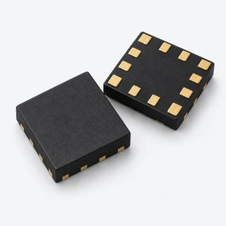 Generic
BMI088 combines a three-axis accelerometer and gyroscope. Bosch designed it for vibration-prone applications including drones and robots.
Sources & technical scope
Illustrative images of generic materials and components.
Related references
BMI088 combines a three-axis accelerometer and gyroscope. Bosch designed it for vibration-prone applications including drones and robots.
Bosch Sensortec · BMI088
Manufacturer offeringBMI088 combines a three-axis accelerometer and gyroscope. Bosch designed it for vibration-prone applications including drones and robots.
Integration requires synchronised timing, sensor alignment and state estimation.
Where this fits
A packaged three-axis accelerometer and three-axis gyroscope supplies six inertial measurement axes.
Sources & technical scope
Illustrative images of generic materials and components.
Link to this detailADIS16470 combines inertial sensors with signal conditioning and factory calibration for sensitivity, bias and alignment. Analog Devices lists robotics among its applications.
This step
Analog Devices · ADIS16470
Manufacturer offeringADIS16470 combines inertial sensors with signal conditioning and factory calibration for sensitivity, bias and alignment. Analog Devices lists robotics among its applications.
The state estimator uses the sensor’s mounting orientation and measurement timestamps.
Where this fits
An IMU supplies acceleration and angular-rate measurements to the robot.
Sources & technical scope
Illustrative images of generic materials and components.
This step
Link to this detailMEMS fabrication creates small mechanical structures within silicon. Bosch’s DRIE process forms deep, controlled trenches.
Production step for Silicon microstructures: Deep reactive-ion etching.
Assembly input to Wafer bonding & cavity sealing: Silicon microstructures.
Related references
Silicon microstructures
MEMS fabrication creates small mechanical structures within silicon. Bosch’s DRIE process forms deep, controlled trenches.
Inputs & supporting parts
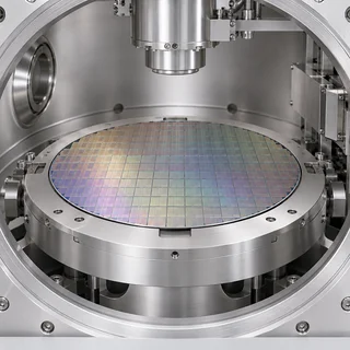
Etching controls trench width, depth and sidewall shape in a MEMS wafer.
Where this fits
Bonding joins wafers and can seal a MEMS cavity.
Sources & technical scope
Illustrative images of generic materials and components.
Related references
Deep etching forms microscopic mechanical structures in silicon. Their geometry defines the inertial sensing structure.
Material input to Deep reactive-ion etching: Etch mask & stop layer.
Production step for Silicon microstructures: Deep reactive-ion etching.
Deep reactive-ion etching
Etching controls trench width, depth and sidewall shape in a MEMS wafer.
Trench geometry and process variation affect the finished structure.
Inputs & supporting parts
A patterned resist or oxide mask protects selected silicon during deep etching.
Where this fits
MEMS fabrication creates small mechanical structures within silicon.
Sources & technical scope
Illustrative images of generic materials and components.
Link to this detailBonding joins wafers and can seal a MEMS cavity. Bosch lists anodic, eutectic and glass-frit methods.
Assembly input to Wafer bonding & cavity sealing: Silicon microstructures.
Checks on Wafer bonding & cavity sealing: Bond inspection.
This step
Related references
Wafer bonding & cavity sealing
Bonding joins wafers and can seal a MEMS cavity. Bosch lists anodic, eutectic and glass-frit methods.
Materials and cavity geometry determine the suitable bonding process.
Inputs & supporting parts
MEMS fabrication creates small mechanical structures within silicon.
Where this fits
Infrared or acoustic inspection can characterise bonded wafer stacks.
Sources & technical scope
Illustrative images of generic materials and components.
This step
Related references
Infrared or acoustic inspection can characterise bonded wafer stacks.
Checks on Wafer bonding & cavity sealing: Bond inspection.
Sequence: Bond inspection → MEMS die packaging.
This step
Related references
Bond inspection
Infrared or acoustic inspection can characterise bonded wafer stacks.
Inputs & supporting parts
Bonding joins wafers and can seal a MEMS cavity.
Where this fits
Sealed sensing structures are separated and electrically connected in a sensor package with readout circuitry.
Sources & technical scope
Illustrative images of generic materials and components.
This step
Related references
Measuring gyroscope bias and scale factor across temperatures provides the data for temperature compensation.
Sequence: Stationary & known-rate readings → Temperature calibration.
Sequence: Temperature calibration → Sensitivity & axis alignment.
Supporting dependency for Factory calibration: Temperature calibration.
Temperature calibration
Gyroscope bias and scale factor can be characterised at multiple temperatures for compensation.
Temperature-dependent bias and sensitivity are calibration dependencies.
Inputs & supporting parts
Stationary readings establish gyroscope bias.
Where this fits
ADI’s ADIS16500 factory calibration characterises sensitivity, bias and alignment of the inertial channels.
Known motion and temperature characterise bias, sensitivity and axis alignment.
Sources & technical scope
Illustrative images of generic materials and components.
Related references
A controlled angular-rate input establishes gyroscope scale factor during calibration.
Production equipment for Stationary & known-rate readings: Known-rate reference.
Known-rate reference
A controlled angular-rate input establishes gyroscope scale factor during calibration.
Where this fits
Stationary readings establish gyroscope bias.
Sources & technical scope
Illustrative images of generic materials and components.
Link to this detailADI’s ADIS16500 factory calibration characterises sensitivity, bias and alignment of the inertial channels.
Sequence: Temperature calibration → Sensitivity & axis alignment.
Supporting dependency for Packaged IMU & board connection: Sensitivity & axis alignment.
Supporting dependency for Calibrated IMU: Sensitivity & axis alignment.
Sequence: Sensitivity & axis alignment → Calibrated IMU.
Sensitivity & axis alignment
ADI’s ADIS16500 factory calibration characterises sensitivity, bias and alignment of the inertial channels.
Installation relates the calibrated sensor axes to the robot’s coordinate system.
Inputs & supporting parts
Gyroscope bias and scale factor can be characterised at multiple temperatures for compensation.
Where this fits
ADIS16500 combines three-axis acceleration and angular-rate sensing with calibration and SPI readout in a surface-mount package.
An IMU supplies acceleration and angular-rate measurements to the robot.
Sources & technical scope
Illustrative images of generic materials and components.
Related references
A patterned resist or oxide mask protects selected silicon during deep etching. A stop layer and endpoint detection control the completed trench depth.
Material input to Deep reactive-ion etching: Etch mask & stop layer.
Etch mask & stop layer
A patterned resist or oxide mask protects selected silicon during deep etching. A stop layer and endpoint detection control the completed trench depth.
Where this fits
Etching controls trench width, depth and sidewall shape in a MEMS wafer.
Sources & technical scope
Illustrative images of generic materials and components.
Link to this detailA capacitive accelerometer suspends a proof mass on springs between sensing electrodes. Motion changes the capacitance measured by the readout circuit.
Used in Accelerometers: Proof mass, springs & electrodes.
Proof mass, springs & electrodes
A capacitive accelerometer suspends a proof mass on springs between sensing electrodes. Motion changes the capacitance measured by the readout circuit.
Where this fits
Three-axis accelerometers measure specific force.
Sources & technical scope
Illustrative images of generic materials and components.
Related references
ADIS16500 combines three-axis acceleration and angular-rate sensing with calibration and SPI readout in a surface-mount package. Board assembly connects power, data and synchronisation signals.
Supporting dependency for Packaged IMU & board connection: Sensitivity & axis alignment.
Used in Packaged IMU & board connection: Conditioning & readout.
Assembly input to Installed alignment: Packaged IMU & board connection.
Used in Calibrated IMU: Packaged IMU & board connection.
Packaged IMU & board connection
ADIS16500 combines three-axis acceleration and angular-rate sensing with calibration and SPI readout in a surface-mount package. Board assembly connects power, data and synchronisation signals.
Inputs & supporting parts
ADI’s ADIS16500 factory calibration characterises sensitivity, bias and alignment of the inertial channels.
Readout electronics digitise the inertial measurements.
Where this fits
The sensor axes must be related to the robot’s body frame.
An IMU supplies acceleration and angular-rate measurements to the robot.
Sources & technical scope
Illustrative images of generic materials and components.
Related references
Stationary readings establish gyroscope bias. Known rotation rates establish sensitivity; temperature readings relate both measurements to operating conditions.
Production equipment for Stationary & known-rate readings: Known-rate reference.
Sequence: Sensing & readout integration → Stationary & known-rate readings.
Sequence: Stationary & known-rate readings → Temperature calibration.
Related references
Stationary & known-rate readings
Stationary readings establish gyroscope bias. Known rotation rates establish sensitivity; temperature readings relate both measurements to operating conditions.
Inputs & supporting parts
A controlled angular-rate input establishes gyroscope scale factor during calibration.
Acceleration and angular-rate sensing elements connect to signal-conditioning and digital readout electronics.
Where this fits
Gyroscope bias and scale factor can be characterised at multiple temperatures for compensation.
Sources & technical scope
Illustrative images of generic materials and components.
Related references
Sealed sensing structures are separated and electrically connected in a sensor package with readout circuitry. Package architecture varies between integrated MEMS chips and complete calibrated IMU modules.
Sequence: Bond inspection → MEMS die packaging.
Sequence: MEMS die packaging → Six-axis MEMS package.
MEMS die packaging
Sealed sensing structures are separated and electrically connected in a sensor package with readout circuitry. Package architecture varies between integrated MEMS chips and complete calibrated IMU modules.
Inputs & supporting parts
Infrared or acoustic inspection can characterise bonded wafer stacks.
Where this fits
A packaged three-axis accelerometer and three-axis gyroscope supplies six inertial measurement axes.
Sources & technical scope
Illustrative images of generic materials and components.
Related references
Acceleration and angular-rate sensing elements connect to signal-conditioning and digital readout electronics. Calibration then characterises sensitivity, bias and axis alignment.
Sequence: Six-axis MEMS package → Sensing & readout integration.
Sequence: Sensing & readout integration → Stationary & known-rate readings.
Sensing & readout integration
Acceleration and angular-rate sensing elements connect to signal-conditioning and digital readout electronics. Calibration then characterises sensitivity, bias and axis alignment.
Inputs & supporting parts
A packaged three-axis accelerometer and three-axis gyroscope supplies six inertial measurement axes.
Where this fits
Stationary readings establish gyroscope bias.
Sources & technical scope
Illustrative images of generic materials and components.
Related references
Production equipment
- EV GroupWafer bonding & alignment systems
Aligned wafer bonding joins sensor layers and seals MEMS structures. Fusion and hybrid bonding also connect layers in stacked image sensors and advanced semiconductor packages.
Wafer bonding →EuropeSources
IMUs, image sensors and compute · bonded wafers and device layers
EV Group · wafer bonding technologies and systems

Market context
Bosch integrated MEMS production scale

>1bnIntegrated MEMS sensors shipped
Broad sensor production across consumer and other applications; not robot IMU shipments or inertial-sensor market share.
Livox

MEVIUS2 pairs two Livox MID-360 LiDARs with a TIER IV C1 camera and NVIDIA Jetson compute. The design uses the LiDAR/IMU input alongside camera data.
Companies
Browse components →BoschSensortec BMI-series MEMS IMUsLivoxa purchased perception stackTDKSupply connection · Waveshare
Explore documented supply relationships →
Cameras / depth vision
Images and depth maps locate objects, guide manipulation and reveal obstacles. Placement, calibration and lighting shape the usable view.
Inside a stereo depth camera
Two infrared cameras estimate depth. A projector adds texture for matching, while the RGB camera records colour.
Drag to rotate · scroll to zoom
Loading CAD model…
Source & model scope
Official RealSense ROS geometry, with the optical apertures labelled in their original positions. Colour identifies each optical function. Optics view dims the enclosure and labels the front apertures. Rotate, isolate or focus a part to inspect it; electronics remain exterior geometry.
Original design · Apache 2.0 licence · Conversion notes · Upstream notices
Architecture, materials & specificationsArchitecture options, material requirements and integration constraints
Architecture options
| Approach | Mechanism | Advantages | Trade-offs |
|---|---|---|---|
| Passive stereo | Matches corresponding features in two calibrated images. | Estimates depth without a projector. | Plain surfaces may have too little texture; darkness and reflections also cause problems. |
| Active stereo | Adds projected texture to help the two cameras match features. | Improves matching on surfaces with little natural texture. | Projector power, working range and ambient illumination limit the benefit. |
| Time of flight | Estimates distance from the travel of emitted light. | Does not need image features for stereo matching. | Indirect reflections, target reflectivity and ambient light can distort depth. |
Specifications & operating limits
Image resolution counts pixels; depth accuracy describes distance error. Field of view is the visible angle, and minimum working distance is the nearest useful range. Frame rate counts captures, whereas latency includes the time needed to deliver and process them.
Materials & constraints
- Optical glass & windows
- Transmit and focus light at the required wavelengths.
- Image sensors
- Convert light into electrical measurements.
- Boards & housing
- Carry processing, connections and mechanical protection.
Dependencies & engineering limits
- Assembly & calibration
- Stereo depth depends on the relative positions and optics of two cameras. Camera calibration measures that geometry, and depth checks quantify the assembled system’s error.
- Mounting & depth quality
- Mechanical shifts can disturb camera geometry. Mount protection and calibration checks after impact or repair preserve the camera geometry. Structure & materials
- Scene & missing measurements
- Plain, shiny or transparent surfaces can defeat depth estimation. Missing or unreliable depth is different from a measured surface; that distinction affects how the robot interprets obstacles.
- Images & bandwidth & delay
- Higher resolution and frame rate create more data to move and process. Synchronisation and processing latency determine how current the robot’s view is when it acts. Compute & control
Manufacturing & assembly
Parts & processes
No matching parts or examples.
Representative industrial route. Separate branches supply lenses and image sensors. A stereo camera combines two imaging paths in a rigid assembly, then calibrates them to measure depth.
Optics
Sensors
Integration / calibration · Representative route. Finished lenses and sensors join before calibration of the pair.
Related parts & processes 5
Functional chain · Representative route. A stereo-camera route; time-of-flight and structured-light systems use different depth measurement.
Related parts & processes 3
Manufacturing · Representative route. Glass elements and barrel parts meet at final assembly.
Related parts & processes 3
Manufacturing · Representative route. Sony’s colour-sensor flow from wafers to tested packages.
Related parts & processes 1
Assembly · Representative route. Separate inputs converge into the supplied component.
Related parts & processes 4
A stereo pair captures two views of the same scene.
Design alternative for Lenses & image sensors: Global-shutter CMOS sensor.
Design alternative for Lenses & image sensors: Imaging lens.
Assembly input to Lenses & image sensors: Packaged image sensor.
Assembly input to Lenses & image sensors: Imaging lens.
Assembly input to Baseline & mounting: Lenses & image sensors.
Assembly input to Rigid stereo assembly: Lenses & image sensors.
This step
Lenses & image sensors
A stereo pair captures two views of the same scene.
Both cameras’ optics and positions matter.
Inputs & supporting parts
A global-shutter CMOS sensor captures the image before camera-level processing and depth estimation.
Lens choice sets sensor coverage, field of view and resolving requirements for a given working distance.
Final package measurements check the image sensor before shipment.
Where this fits
The separation and relative orientation establish the stereo geometry.
Two lens-and-sensor units share a fixed mount.
Sources & technical scope
Illustrative images of generic materials and components.
This step
Related references
The separation and relative orientation establish the stereo geometry.
Assembly input to Baseline & mounting: Lenses & image sensors.
Supporting dependency for Baseline & mounting: Protected installation.
Checks on Baseline & mounting: Calibration & rectification.
Assembly input to Stereo depth camera: Baseline & mounting.
Baseline & mounting
The separation and relative orientation establish the stereo geometry.
A mechanical shift can disturb calibration.
Inputs & supporting parts
A stereo pair captures two views of the same scene.
The mount protects calibrated geometry during movement and handling.
Where this fits
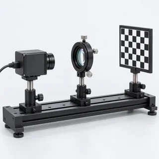
Calibration describes the camera geometry; rectification aligns the views for matching.
Two lens-and-sensor paths, readout electronics and a rigid baseline form the stereo camera.
Sources & technical scope
Illustrative images of generic materials and components.
Link to this detailCalibration describes the camera geometry; rectification aligns the views for matching.
Checks on Baseline & mounting: Calibration & rectification.
Supporting dependency for Calibration & rectification: Lens & sensor calibration.
Supporting dependency for Calibration & rectification: Stereo alignment verification.
Measurement or signal input to Stereo matching: Calibration & rectification.
Calibration & rectification
Calibration describes the camera geometry; rectification aligns the views for matching.
Depth accuracy depends on the calibrated camera assembly.
Inputs & supporting parts
The separation and relative orientation establish the stereo geometry.
Calibration determines focal length and lens distortion for each camera.
A calibration target checks the paired cameras; strong mechanical disturbance can require recalibration.
Where this fits
Matching corresponding image features produces disparity, from which depth is calculated.
Sources & technical scope
Illustrative images of generic materials and components.
This step
Related references
Matching corresponding image features produces disparity, from which depth is calculated.
Measurement or signal input to Stereo matching: Calibration & rectification.
Optional component of Stereo matching: Texture projector.
Measurement or signal input to Depth observations: Stereo matching.
This step
Stereo matching
Matching corresponding image features produces disparity, from which depth is calculated.
Occlusion and insufficient texture leave uncertain or missing depth.
Inputs & supporting parts
Calibration describes the camera geometry; rectification aligns the views for matching.
Active stereo adds projected texture to help matching.
Where this fits
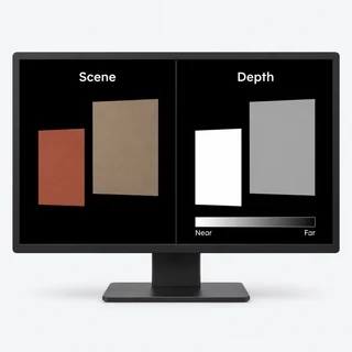
Depth and image data feed the robot’s perception software.
Sources & technical scope
Illustrative images of generic materials and components.
This step
Link to this detailDepth and image data feed the robot’s perception software.
Measurement or signal input to Depth observations: Stereo matching.
Supporting dependency for Depth observations: Synchronisation.
Related references
Depth observations
Compute & control →Depth and image data feed the robot’s perception software.
Resolution and frame rate also increase bandwidth and processing demands.
Inputs & supporting parts
Matching corresponding image features produces disparity, from which depth is calculated.
Sensor timing must be consistent with other measurements used by the robot.
Sources & technical scope
Illustrative images of generic materials and components.
Related references
Active stereo adds projected texture to help matching.
Optional component of Stereo matching: Texture projector.
This step
Texture projector
Active stereo adds projected texture to help matching.
Used in active-stereo systems.
Where this fits
Matching corresponding image features produces disparity, from which depth is calculated.
Sources & technical scope
Illustrative images of generic materials and components.
This step
Link to this detailThe mount protects calibrated geometry during movement and handling.
Supporting dependency for Baseline & mounting: Protected installation.
Supporting dependency for Rigid stereo assembly: Protected installation.
Protected installation
Structure & materials →The mount protects calibrated geometry during movement and handling.
Mechanical disturbance can change the calibrated camera geometry.
Where this fits
The separation and relative orientation establish the stereo geometry.
Two lens-and-sensor units share a fixed mount.
Sources & technical scope
Illustrative images of generic materials and components.
Related references
Sensor timing must be consistent with other measurements used by the robot.
Supporting dependency for Depth observations: Synchronisation.
Supporting dependency for Stereo depth camera: Synchronisation.
Synchronisation
IMUs & inertial sensing →Sensor timing must be consistent with other measurements used by the robot.
Transport and processing latency affect observation age.
Where this fits
Depth and image data feed the robot’s perception software.
Two lens-and-sensor paths, readout electronics and a rigid baseline form the stereo camera.
Sources & technical scope
Illustrative images of generic materials and components.
Related references
A global-shutter CMOS sensor captures the image before camera-level processing and depth estimation.
Design alternative for Lenses & image sensors: Global-shutter CMOS sensor.
Related references
Global-shutter CMOS sensor
A global-shutter CMOS sensor captures the image before camera-level processing and depth estimation.
Colour and monochrome variants have different ordering codes and interface options.
Where this fits
A stereo pair captures two views of the same scene.
Examples from industry 1
 Generic
AR0234CS is a global-shutter CMOS image-sensor family. onsemi lists colour and monochrome configurations with digital image interfaces.
Sources & technical scope
Illustrative images of generic materials and components.
Related references
Lens choice sets sensor coverage, field of view and resolving requirements for a given working distance.
Assembly input to Imaging lens: Barrel, spacers & focus mechanism.
Production step for Imaging lens: Lens-element assembly.
Design alternative for Lenses & image sensors: Imaging lens.
Assembly input to Lenses & image sensors: Imaging lens.
Imaging lens
Lens choice sets sensor coverage, field of view and resolving requirements for a given working distance.
Sensor format, mount and working distance determine the required lens geometry.
Inputs & supporting parts
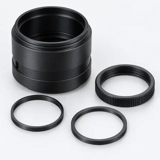
Machined seats, spacers and retaining parts position the elements inside the imaging lens.
Clean elements sit in precision barrel seats, separated by spacers and secured with retaining rings.
Where this fits
A stereo pair captures two views of the same scene.
Examples from industry 1
 Generic
Edmund Optics offers fixed-focal-length lenses with different sensor coverage, mounts, resolving power and wavelength ranges, including ruggedised designs.
Sources & technical scope
Illustrative images of generic materials and components.
Related references
AR0234CS is a global-shutter CMOS image-sensor family. onsemi lists colour and monochrome configurations with digital image interfaces.
onsemi · AR0234CS
Manufacturer offeringAR0234CS is a global-shutter CMOS image-sensor family. onsemi lists colour and monochrome configurations with digital image interfaces.
Sensor format, shutter timing and interfaces determine the optics and processing around the chip.
Where this fits
A global-shutter CMOS sensor captures the image before camera-level processing and depth estimation.
Sources & technical scope
Illustrative images of generic materials and components.
Link to this detailEdmund Optics offers fixed-focal-length lenses with different sensor coverage, mounts, resolving power and wavelength ranges, including ruggedised designs.
Edmund Optics · machine-vision lenses
Manufacturer offeringEdmund Optics offers fixed-focal-length lenses with different sensor coverage, mounts, resolving power and wavelength ranges, including ruggedised designs.
Sensor size and lens focal length set the field of view; the lens mount fixes the optical alignment.
Where this fits
Lens choice sets sensor coverage, field of view and resolving requirements for a given working distance.
Sources & technical scope
Illustrative images of generic materials and components.
Link to this detailOptical-grade glass blanks provide the material for the documented ground-and-polished imaging-lens route.
Material input to Grinding, polishing & centring: Optical glass blanks.
Optical glass blanks
Optical-grade glass blanks provide the material for the documented ground-and-polished imaging-lens route.
Moulded optics and other materials are alternatives.
Where this fits
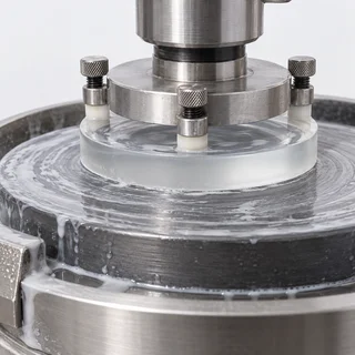
Lens elements are shaped, polished and centred to align their optical and mechanical axes.
Sources & technical scope
Illustrative images of generic materials and components.
Link to this detailLens elements are shaped, polished and centred to align their optical and mechanical axes.
Material input to Grinding, polishing & centring: Optical glass blanks.
Sequence: Grinding, polishing & centring → Cleaning & optical coating.
Grinding, polishing & centring
Lens elements are shaped, polished and centred to align their optical and mechanical axes.
Surface shape and centration require metrology during manufacture.
Inputs & supporting parts
Optical-grade glass blanks provide the material for the documented ground-and-polished imaging-lens route.
Where this fits
Clean elements receive antireflection coatings before lens assembly.
Sources & technical scope
Illustrative images of generic materials and components.
Link to this detailClean elements receive antireflection coatings before lens assembly.
Sequence: Grinding, polishing & centring → Cleaning & optical coating.
Assembly input to Lens-element assembly: Cleaning & optical coating.
Cleaning & optical coating
Clean elements receive antireflection coatings before lens assembly.
Coating choice follows the intended optical band and lens design.
Inputs & supporting parts
Lens elements are shaped, polished and centred to align their optical and mechanical axes.
Where this fits
Clean elements sit in precision barrel seats, separated by spacers and secured with retaining rings.
Sources & technical scope
Illustrative images of generic materials and components.
Link to this detailThe barrel, spacers and retaining parts hold lens elements in alignment and set their separation.
Assembly input to Imaging lens: Barrel, spacers & focus mechanism.
Assembly input to Lens-element assembly: Barrel, spacers & focus mechanism.
Related references
Barrel, spacers & focus mechanism
Machined seats, spacers and retaining parts position the elements inside the imaging lens.
Tilt and decentring affect image quality.
Where this fits
Lens choice sets sensor coverage, field of view and resolving requirements for a given working distance.
Clean elements sit in precision barrel seats, separated by spacers and secured with retaining rings.
Sources & technical scope
Illustrative images of generic materials and components.
Related references
The completed lens is checked for alignment and image performance; demanding applications can use MTF testing.
Checks on Lens-element assembly: Image quality & alignment test.
Image quality & alignment test
The completed lens is checked for alignment and image performance; demanding applications can use MTF testing.
Camera-level calibration characterises the combined lens and sensor.
Inputs & supporting parts
Clean elements sit in precision barrel seats, separated by spacers and secured with retaining rings.
Sources & technical scope
Illustrative images of generic materials and components.
Link to this detailPixel and logic circuits are fabricated on separate wafers, then bonded to form the stacked image sensor. Packaging follows wafer fabrication and bonding.
Sequence: Pixel & logic wafers → Pixel–logic wafer bonding.
Pixel & logic wafers
Pixel wafers contain photodiodes and metal wiring. Separate logic wafers supply the readout circuitry before the two wafer structures are joined.
Where this fits
Sony’s stacked CMOS route joins pixel and logic wafers before forming colour filters and microlenses.
Sources & technical scope
Illustrative images of generic materials and components.
Link to this detailColour filters and on-chip lenses are formed above the pixels in Sony’s colour-sensor flow.
Sequence: Pixel–logic wafer bonding → Colour filters & microlenses.
Sequence: Colour filters & microlenses → Wafer test & dicing.
Colour filters & microlenses
Colour filters and on-chip lenses are formed above the pixels in Sony’s colour-sensor flow.
This colour-filter step applies to colour sensors.
Inputs & supporting parts
Sony’s stacked CMOS route joins pixel and logic wafers before forming colour filters and microlenses.
Where this fits
Electrical and reliability checks identify usable devices at wafer level.
Sources & technical scope
Illustrative images of generic materials and components.
Link to this detailElectrical and reliability checks identify usable devices at wafer level. Dicing separates the individual sensor dies for packaging.
Sequence: Colour filters & microlenses → Wafer test & dicing.
Assembly input to Die attach, bonds & encapsulation: Wafer test & dicing.
Wafer test & dicing
Electrical and reliability checks identify usable devices at wafer level. Dicing separates the individual sensor dies for packaging.
Equipment for this step →Inputs & supporting parts
Colour filters and on-chip lenses are formed above the pixels in Sony’s colour-sensor flow.
Where this fits
In Sony’s documented flow, separated chips attach to a lead frame, receive metallic electrical connections and are sealed with resin before final measurement.
Sources & technical scope
Illustrative images of generic materials and components.
Link to this detailFinal package measurements check the image sensor before shipment. The tested device supplies image data to the camera electronics.
Production step for Packaged image sensor: Die attach, bonds & encapsulation.
Assembly input to Lenses & image sensors: Packaged image sensor.
Assembly input to Stereo depth camera: Packaged image sensor.
Packaged image sensor
Final package measurements check the image sensor before shipment. The tested device supplies image data to the camera electronics.
Lens manufacture and stereo alignment are separate dependencies.
Inputs & supporting parts
In Sony’s documented flow, separated chips attach to a lead frame, receive metallic electrical connections and are sealed with resin before final measurement.
Where this fits
A stereo pair captures two views of the same scene.
Two lens-and-sensor paths, readout electronics and a rigid baseline form the stereo camera.
Sources & technical scope
Illustrative images of generic materials and components.
Link to this detailCalibration determines focal length and lens distortion for each camera.
Checks on Rigid stereo assembly: Lens & sensor calibration.
Sequence: Lens & sensor calibration → Stereo alignment verification.
Supporting dependency for Calibration & rectification: Lens & sensor calibration.
Related references
Lens & sensor calibration
Calibration determines focal length and lens distortion for each camera.
These intrinsic parameters are separate from the relative pose of a stereo pair.
Inputs & supporting parts
Two lens-and-sensor units share a fixed mount.
Where this fits
A calibration target checks the paired cameras; strong mechanical disturbance can require recalibration.
Calibration describes the camera geometry; rectification aligns the views for matching.
Sources & technical scope
Illustrative images of generic materials and components.
Related references
Stereo depth depends on the cameras’ relative positions. Mechanical disturbance can change that relationship even if both sensors still produce images.
Sequence: Lens & sensor calibration → Stereo alignment verification.
Production equipment for Stereo alignment verification: Calibration grid.
Checks on Stereo alignment verification: Calibration residual & saved parameters.
Supporting dependency for Calibration & rectification: Stereo alignment verification.
Related references
Stereo alignment verification
A calibration target checks the paired cameras; strong mechanical disturbance can require recalibration.
Movement between the cameras changes their calibrated geometry.
Inputs & supporting parts
Calibration determines focal length and lens distortion for each camera.
A known grid is observed at multiple poses.
Where this fits
Reprojection error compares observed grid corners with the calibrated model’s predictions.
Calibration describes the camera geometry; rectification aligns the views for matching.
Sources & technical scope
Illustrative images of generic materials and components.
Related references
Clean elements sit in precision barrel seats, separated by spacers and secured with retaining rings. Focus and iris mechanisms are assembled around the optical stack.
Assembly input to Lens-element assembly: Cleaning & optical coating.
Assembly input to Lens-element assembly: Barrel, spacers & focus mechanism.
Checks on Lens-element assembly: Image quality & alignment test.
Production step for Imaging lens: Lens-element assembly.
Assembly input to Stereo depth camera: Lens-element assembly.
Lens-element assembly
Clean elements sit in precision barrel seats, separated by spacers and secured with retaining rings. Focus and iris mechanisms are assembled around the optical stack.
Inputs & supporting parts
Clean elements receive antireflection coatings before lens assembly.
Machined seats, spacers and retaining parts position the elements inside the imaging lens.
Where this fits
The completed lens is checked for alignment and image performance; demanding applications can use MTF testing.
Lens choice sets sensor coverage, field of view and resolving requirements for a given working distance.
Two lens-and-sensor paths, readout electronics and a rigid baseline form the stereo camera.
Sources & technical scope
Illustrative images of generic materials and components.
Related references
Two lens-and-sensor units share a fixed mount. Their separation and relative orientation form the geometry measured during stereo calibration.
Assembly input to Rigid stereo assembly: Lenses & image sensors.
Supporting dependency for Rigid stereo assembly: Protected installation.
Checks on Rigid stereo assembly: Lens & sensor calibration.
Sequence: Rigid stereo assembly → Calibration residual & saved parameters.
Rigid stereo assembly
Two lens-and-sensor units share a fixed mount. Their separation and relative orientation form the geometry measured during stereo calibration.
Inputs & supporting parts
A stereo pair captures two views of the same scene.
The mount protects calibrated geometry during movement and handling.
Where this fits
Calibration determines focal length and lens distortion for each camera.
Reprojection error compares observed grid corners with the calibrated model’s predictions.
Sources & technical scope
Illustrative images of generic materials and components.
Related references
A known grid is observed at multiple poses. Its geometry links image coordinates to the camera model and the relative pose of the pair.
Production equipment for Stereo alignment verification: Calibration grid.
Calibration grid
A known grid is observed at multiple poses. Its geometry links image coordinates to the camera model and the relative pose of the pair.
Where this fits
A calibration target checks the paired cameras; strong mechanical disturbance can require recalibration.
Sources & technical scope
Illustrative images of generic materials and components.
Link to this detailReprojection error compares observed grid corners with the calibrated model’s predictions. Save the accepted parameters to the camera before using its depth output.
Checks on Stereo alignment verification: Calibration residual & saved parameters.
Sequence: Rigid stereo assembly → Calibration residual & saved parameters.
Production step for Stereo depth camera: Calibration residual & saved parameters.
Calibration residual & saved parameters
Reprojection error compares observed grid corners with the calibrated model’s predictions. Save the accepted parameters to the camera before using its depth output.
Inputs & supporting parts
A calibration target checks the paired cameras; strong mechanical disturbance can require recalibration.
Two lens-and-sensor units share a fixed mount.
Where this fits
Two lens-and-sensor paths, readout electronics and a rigid baseline form the stereo camera.
Sources & technical scope
Illustrative images of generic materials and components.
Link to this detailIn Sony’s documented flow, separated chips attach to a lead frame, receive metallic electrical connections and are sealed with resin before final measurement.
Assembly input to Die attach, bonds & encapsulation: Wafer test & dicing.
Production step for Packaged image sensor: Die attach, bonds & encapsulation.
Die attach, bonds & encapsulation
In Sony’s documented flow, separated chips attach to a lead frame, receive metallic electrical connections and are sealed with resin before final measurement.
Inputs & supporting parts
Electrical and reliability checks identify usable devices at wafer level.
Where this fits
Final package measurements check the image sensor before shipment.
Sources & technical scope
Illustrative images of generic materials and components.
Link to this detailSony’s stacked CMOS route joins pixel and logic wafers before forming colour filters and microlenses.
Sequence: Pixel & logic wafers → Pixel–logic wafer bonding.
Sequence: Pixel–logic wafer bonding → Colour filters & microlenses.
Pixel–logic wafer bonding
Sony’s stacked CMOS route joins pixel and logic wafers before forming colour filters and microlenses.
Equipment for this step →Inputs & supporting parts
Pixel wafers contain photodiodes and metal wiring.
Where this fits
Colour filters and on-chip lenses are formed above the pixels in Sony’s colour-sensor flow.
Sources & technical scope
Illustrative images of generic materials and components.
Link to this detailTwo lens-and-sensor paths, readout electronics and a rigid baseline form the stereo camera. Stored calibration and stereo processing convert the paired images into depth.
Production step for Stereo depth camera: Calibration residual & saved parameters.
Assembly input to Stereo depth camera: Lens-element assembly.
Assembly input to Stereo depth camera: Packaged image sensor.
Assembly input to Stereo depth camera: Baseline & mounting.
Supporting dependency for Stereo depth camera: Synchronisation.
Stereo depth camera
Two lens-and-sensor paths, readout electronics and a rigid baseline form the stereo camera. Stored calibration and stereo processing convert the paired images into depth.
Inputs & supporting parts
Reprojection error compares observed grid corners with the calibrated model’s predictions.
Clean elements sit in precision barrel seats, separated by spacers and secured with retaining rings.
Final package measurements check the image sensor before shipment.
The separation and relative orientation establish the stereo geometry.
Sensor timing must be consistent with other measurements used by the robot.
Sources & technical scope
Illustrative images of generic materials and components.
Related references
Production equipment
- DISCOWafer dicing equipment
Blade and laser systems separate semiconductor wafers into individual dies before package assembly.
Die separation →JapanSources
Cameras and compute · semiconductor dies
DISCO · precision processing equipment - SatislohPrecision lens grinding & polishing
Grinding, polishing and centring machines shape precision lens surfaces. Coating equipment adds the optical layers needed for transmission and reflection.
Lens manufacture →EuropeSources
Cameras and lidar · manufactured lenses
Satisloh · precision optics manufacturing equipment - EV GroupWafer bonding & alignment systems
Aligned wafer bonding joins sensor layers and seals MEMS structures. Fusion and hybrid bonding also connect layers in stacked image sensors and advanced semiconductor packages.
Wafer bonding →EuropeSources
IMUs, image sensors and compute · bonded wafers and device layers
EV Group · wafer bonding technologies and systems


Market context
Upstream image sensors
≈50%Sony · global CMOS sensor revenue
Sensor chips are a different market from complete depth cameras or robotics perception.
RealSense

Cognex agreed to acquire RealSense for approximately US$500 million in cash, extending its industrial machine-vision business into robotic depth perception.
Orbbec

Orbbec broke ground on a Vietnam factory for 3D sensors and intelligent hardware, targeting production in 2027. Its Foshan factory is already ramping. H1 2026 sales of vision systems to robot customers more than doubled year on year.
Livox
MEVIUS2 pairs two Livox MID-360 LiDARs with a TIER IV C1 camera and NVIDIA Jetson compute. The design uses the LiDAR/IMU input alongside camera data.
Unitree
Go2 EDU adds a depth camera and supports a separate high-compute module, including Orin options. The standard onboard eight-core CPU remains a distinct computing layer.
Ouster

Ouster reports acquiring Stereolabs on 4 February 2026, bringing ZED cameras, digital LiDAR, embedded compute and perception software into one supplier group.
Companies
Browse components →RealSenseSupply connection · MagicLabLivoxa purchased perception stackUnitreeperception and compute by configuration
Explore documented supply relationships →LiDAR
Measures distance with laser light to map surroundings and locate obstacles. Field of view and mounting determine which surfaces the robot sees.
How time-of-flight ranging works
Follow a light pulse from emitter to surface and back to the receiver. Inspect the optical paths, detector and timing electronics.
Drag to rotate · scroll to zoom
Loading model…
Source & model scope
Original pulsed time-of-flight illustration. Light travel is slowed down and coloured; optical paths, detector grid and board details are schematic. This explains one ranging principle, not the internal layout of the L515 or a specific ST product. Original Korthos geometry.
STMicroelectronics · time-of-flight sensing · Model scope & reuseInside a compact LiDAR
A discontinued MEMS-scanning LiDAR, shown as an architecture reference. Inspect its enclosure, front window and internal assembly.
Drag to rotate · scroll to zoom
Loading CAD model…
Source & model scope
Official RealSense ROS geometry. Inside view removes the housing and front window to expose the source assembly. Colours distinguish existing internal surfaces; they do not identify material grades or individual circuit functions. Separated parts shows the three main groups. L515 is a discontinued architecture reference.
Original design · Apache 2.0 licence · Conversion notes · Upstream notices
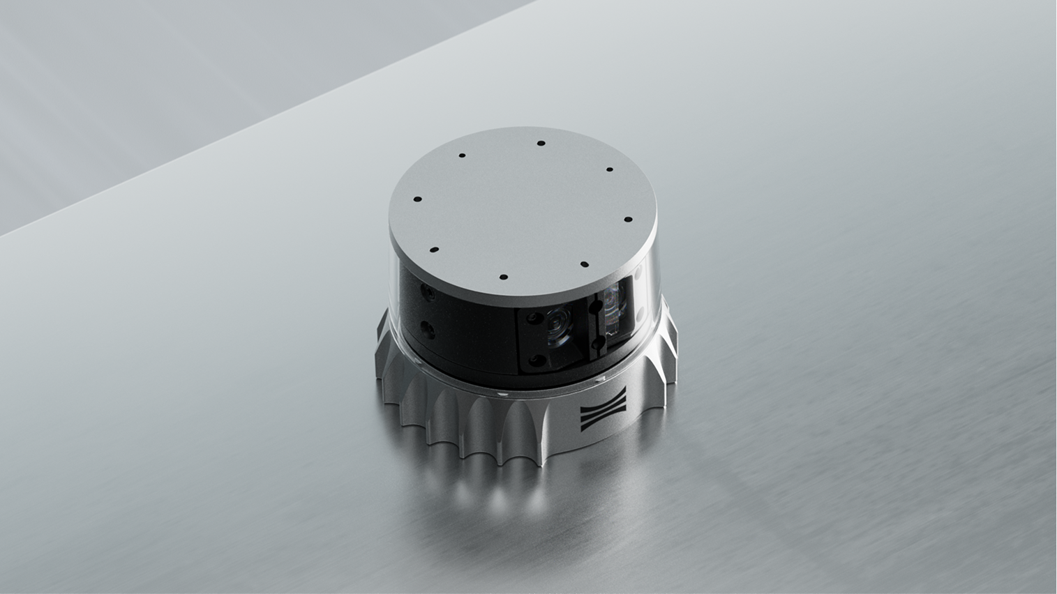

Architecture, materials & specificationsArchitecture options, material requirements and integration constraints
Architecture options
“Solid state” covers several architectures. Field of view, resolution and scan pattern vary between them.
| Approach | Mechanism | Advantages | Trade-offs |
|---|---|---|---|
| Rotating scanner | A rotating assembly sweeps measurements around the sensor. | Can provide wide surrounding coverage from one mounting position. | Moving hardware and the sensor’s size constrain packaging. |
| Beam steering | A mirror or another steering mechanism directs measurements within a field of view. | Can concentrate measurements within a chosen area. | Coverage is design-specific; some systems still contain small moving parts. |
| Flash illumination | Illuminates an area and measures returns across a detector array. | Captures an area without sequentially steering a beam across it. | Illumination power, range and detector resolution constrain useful coverage. |
Specifications & operating limits
Range is specified for particular targets and conditions. Field of view describes coverage; angular resolution describes spacing between measurements. Scan pattern and frame rate describe how those points cover the scene over time.
Materials & constraints
- Laser emitters
- Produce the outgoing light.
- Photodetectors
- Measure the returned signal.
- Optical elements
- Direct and transmit light; materials depend on wavelength.
Dependencies & engineering limits
- Optical assembly & calibration
- Emitter, receiver and scanning geometry determine the direction and distance assigned to each return. Optical alignment and calibration determine how returns become measurements.
- Placement & blind spots
- A limb, cover or payload can block the field of view. The visible area changes as those parts move, even when the sensor’s own field of view is unchanged. Structure & materials
- Window condition & returns
- Dirt or damage on the optical window can degrade measurements. Cleaning materials and procedures are sensor-specific; aggressive cleaning can damage the window.
- Motion & mapping error
- A moving robot changes position during a scan. Timing and motion compensation are needed to combine points with camera, joint and inertial measurements consistently. Compute & control
Manufacturing & assembly
Parts & processes
No matching parts or examples.
Representative industrial route. A pulsed time-of-flight lidar combines a ranging front end with a scan mechanism or fixed angular channels. Range, direction and timing must be calibrated together.
Transmit
Receive
Other routes
Assembly · Representative route. An ADC-based pulsed ranging reference; scanning is a separate subsystem.
Related parts & processes 5
Functional chain · Representative route. The measurement chain is separate from the product’s particular scanning mechanism.
Related parts & processes 5
Functional chain · Representative route. Threshold detection and time-to-digital conversion form one receiver architecture.
Related parts & processes 3
Integration / calibration · Representative route. The ranging front end needs angular sampling and coordinate calibration to produce a point cloud.
Related parts & processes 6
Assembly · Representative route. Separate inputs converge into the supplied component.
Related parts & processes 5
A time-of-flight LiDAR sends light toward the scene.
Design alternative for Laser emitter: Pulsed infrared laser.
Supporting dependency for Laser emitter: Laser pulse driver.
Measurement or signal input to Receiver & optics: Laser emitter.
Assembly input to Transmit collimation optics: Laser emitter.
Assembly input to Ranging & scan assembly: Laser emitter.
Assembly input to Time-of-flight lidar: Laser emitter.
This step
Laser emitter
A time-of-flight LiDAR sends light toward the scene.
Wavelength and emission architecture are product-specific.
Inputs & supporting parts
A pulsed 905 nm emitter is one light-source option for time-of-flight ranging.
Pulse-drive electronics control the emitted optical waveform in a pulsed time-of-flight design.
Where this fits
Optics collect the returning light for detection.
A collimating lens limits laser-beam divergence.
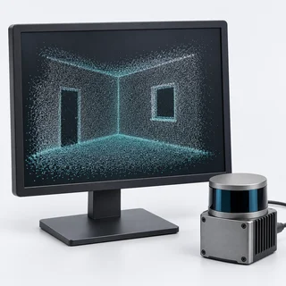
The emitter, receiver and ranging electronics join an angular-sampling system and enclosure.
The ranging front end, angular-sampling mechanism or channel array, electronics and optical enclosure form the lidar.
Sources & technical scope
Illustrative images of generic materials and components.
This step
Related references
Optics collect the returning light for detection.
Measurement or signal input to Receiver & optics: Laser emitter.
Supporting dependency for Receiver & optics: Window & enclosure.
Design alternative for Receiver & optics: Avalanche photodiode.
Supporting dependency for Receiver & optics: Transmit & receive overlap.
Measurement or signal input to Return timing: Receiver & optics.
Measurement or signal input to Photocurrent amplification: Receiver & optics.
Assembly input to Emitter–receiver assembly: Receiver & optics.
Checks on Receiver & optics: Return-signal limits.
Assembly input to Ranging & scan assembly: Receiver & optics.
Assembly input to Time-of-flight lidar: Receiver & optics.
This step
Receiver & optics
Optics collect the returning light for detection.
Reflectivity, ambient light and obscuration affect returns.
Inputs & supporting parts
A time-of-flight LiDAR sends light toward the scene.
The optical window protects the sensor while passing the measurement light.
An avalanche photodiode adds internal gain when detecting optical returns.
Overlapping transmit and receive fields allow reflected pulses to reach the detector through the receive optics.
Where this fits
The elapsed travel time is converted into a range measurement.
A transimpedance amplifier converts the detector’s small current into a usable voltage.
The TI TIDA-01187 reference combines a pulsed 905 nm emitter, collimating optics, a photoreceiver and focusing optics with separate drive and receive electronics.
Background light and target reflectivity affect the detectable return and receiver saturation.
The emitter, receiver and ranging electronics join an angular-sampling system and enclosure.
The ranging front end, angular-sampling mechanism or channel array, electronics and optical enclosure form the lidar.
Sources & technical scope
Illustrative images of generic materials and components.
This step
Related references
The elapsed travel time is converted into a range measurement.
Measurement or signal input to Return timing: Receiver & optics.
Measurement or signal input to Return timing: Comparator & time conversion.
Design alternative for Return timing: Waveform sampling alternative.
Measurement or signal input to Direction & calibration: Return timing.
Assembly input to Ranging & scan assembly: Return timing.
Assembly input to Time-of-flight lidar: Return timing.
Return timing
The elapsed travel time is converted into a range measurement.
A quoted maximum range assumes stated target and environmental conditions.
Inputs & supporting parts
Optics collect the returning light for detection.
A comparator marks a signal crossing; a time-to-digital converter records its timing.
A high-speed ADC digitises the return waveform for processing, instead of using only threshold-crossing times.
Where this fits
Distance is associated with the direction of each measurement.
The emitter, receiver and ranging electronics join an angular-sampling system and enclosure.
The ranging front end, angular-sampling mechanism or channel array, electronics and optical enclosure form the lidar.
Sources & technical scope
Illustrative images of generic materials and components.
This step
Related references
Distance is associated with the direction of each measurement.
Measurement or signal input to Direction & calibration: Return timing.
Measurement or signal input to Timed point cloud: Direction & calibration.
Assembly input to Ranging & scan assembly: Direction & calibration.
Supporting dependency for Time-of-flight lidar: Direction & calibration.
Direction & calibration
Distance is associated with the direction of each measurement.
Scanning mechanisms and coverage vary by design.
Inputs & supporting parts
The elapsed travel time is converted into a range measurement.
Where this fits
Range and direction form spatial points for perception and mapping.
The emitter, receiver and ranging electronics join an angular-sampling system and enclosure.
The ranging front end, angular-sampling mechanism or channel array, electronics and optical enclosure form the lidar.
Sources & technical scope
Illustrative images of generic materials and components.
This step
Related references
Range and direction form spatial points for perception and mapping.
Measurement or signal input to Timed point cloud: Direction & calibration.
Supporting dependency for Timed point cloud: Mounting & visibility.
Supporting dependency for Timed point cloud: Motion compensation.
Sequence: Range & geometry checks → Timed point cloud.
Timed point cloud
Compute & control →Range and direction form spatial points for perception and mapping.
Sensor data still needs the robot’s motion and timing context.
Inputs & supporting parts
Distance is associated with the direction of each measurement.
Placement determines which parts of the nominal field of view are usable.
Robot motion during a scan affects the combined spatial observation.
Reference-distance measurements and beam-direction calibration establish the relation between range, angle and spatial coordinates.
Sources & technical scope
Illustrative images of generic materials and components.
Related references
The optical window protects the sensor while passing the measurement light.
Supporting dependency for Receiver & optics: Window & enclosure.
Assembly input to Time-of-flight lidar: Window & enclosure.
Window & enclosure
The optical window protects the sensor while passing the measurement light.
Dirt, damage and unsuitable cleaning can degrade performance.
Where this fits
Optics collect the returning light for detection.
The ranging front end, angular-sampling mechanism or channel array, electronics and optical enclosure form the lidar.
Sources & technical scope
Illustrative images of generic materials and components.
Related references
Placement determines which parts of the nominal field of view are usable.
Supporting dependency for Timed point cloud: Mounting & visibility.
Mounting & visibility
Structure & materials →Placement determines which parts of the nominal field of view are usable.
Moving limbs, covers or payloads can create blind spots.
Where this fits
Range and direction form spatial points for perception and mapping.
Sources & technical scope
Illustrative images of generic materials and components.
Link to this detailRobot motion during a scan affects the combined spatial observation.
Supporting dependency for Timed point cloud: Motion compensation.
Motion compensation
IMUs & inertial sensing →Robot motion during a scan affects the combined spatial observation.
Timing and sensor alignment matter when fusing LiDAR and inertial data.
Where this fits
Range and direction form spatial points for perception and mapping.
Sources & technical scope
Illustrative images of generic materials and components.
Link to this detailA pulsed 905 nm emitter is one light-source option for time-of-flight ranging.
Design alternative for Laser emitter: Pulsed infrared laser.
Related references
Pulsed infrared laser
A pulsed 905 nm emitter is one light-source option for time-of-flight ranging.
Pulse control, optics and exposure limits constrain the emitted beam.
Where this fits
A time-of-flight LiDAR sends light toward the scene.
Examples from industry 1
 Generic
ams OSRAM offers the SPL UL90AT03 pulsed infrared laser at 905 nm. The laser and its drive electronics form the transmit side of a pulsed ranging system.
Sources & technical scope
Illustrative images of generic materials and components.
Related references
An avalanche photodiode adds internal gain when detecting optical returns.
Design alternative for Receiver & optics: Avalanche photodiode.
This step
Related references
Avalanche photodiode
An avalanche photodiode adds internal gain when detecting optical returns.
Detector material, wavelength response, bias and electronics determine sensitivity to the returning pulse.
Where this fits
Optics collect the returning light for detection.
Examples from industry 1
 Generic
Hamamatsu offers silicon and InGaAs avalanche photodiodes, arrays and receiver modules. These devices provide internal gain for sensitive optical detection.
Sources & technical scope
Illustrative images of generic materials and components.
This step
Related references
ams OSRAM offers the SPL UL90AT03 pulsed infrared laser at 905 nm. The laser and its drive electronics form the transmit side of a pulsed ranging system.
ams OSRAM · SPL UL90AT03
Manufacturer offeringams OSRAM offers the SPL UL90AT03 pulsed infrared laser at 905 nm. The laser and its drive electronics form the transmit side of a pulsed ranging system.
Optics, pulse control and exposure limits constrain the complete transmitter.
Where this fits
A pulsed 905 nm emitter is one light-source option for time-of-flight ranging.
Sources & technical scope
Illustrative images of generic materials and components.
Link to this detailHamamatsu offers silicon and InGaAs avalanche photodiodes, arrays and receiver modules. These devices provide internal gain for sensitive optical detection.
This step
Hamamatsu · APDs and receiver modules
Manufacturer offeringHamamatsu offers silicon and InGaAs avalanche photodiodes, arrays and receiver modules. These devices provide internal gain for sensitive optical detection.
Detector material and wavelength response determine sensitivity; bias and front-end electronics set gain and noise.
Where this fits
An avalanche photodiode adds internal gain when detecting optical returns.
Sources & technical scope
Illustrative images of generic materials and components.
This step
Link to this detailPulse-drive electronics control the emitted optical waveform in a pulsed time-of-flight design.
Supporting dependency for Laser emitter: Laser pulse driver.
Related references
Laser pulse driver
Pulse-drive electronics control the emitted optical waveform in a pulsed time-of-flight design.
The laser and required optical waveform determine the pulse-driver requirements.
Where this fits
A time-of-flight LiDAR sends light toward the scene.
Sources & technical scope
Illustrative images of generic materials and components.
Related references
Overlapping transmit and receive fields allow reflected pulses to reach the detector through the receive optics.
Supporting dependency for Receiver & optics: Transmit & receive overlap.
Related references
Transmit & receive overlap
Overlapping transmit and receive fields allow reflected pulses to reach the detector through the receive optics.
Optical overlap influences the minimum useful measuring distance.
Where this fits
Optics collect the returning light for detection.
Sources & technical scope
Illustrative images of generic materials and components.
Related references
The receiver converts detector current into a voltage signal. Noise and saturation limit detection of the returned light.
Measurement or signal input to Photocurrent amplification: Receiver & optics.
Measurement or signal input to Comparator & time conversion: Photocurrent amplification.
Related references
Photocurrent amplification
A transimpedance amplifier converts the detector’s small current into a usable voltage.
Noise, offset and saturation constrain the receive path.
Inputs & supporting parts
Optics collect the returning light for detection.
Where this fits
A comparator marks a signal crossing; a time-to-digital converter records its timing.
Sources & technical scope
Illustrative images of generic materials and components.
Related references
A comparator marks a signal crossing; a time-to-digital converter records its timing.
Measurement or signal input to Comparator & time conversion: Photocurrent amplification.
Measurement or signal input to Return timing: Comparator & time conversion.
Related references
Comparator & time conversion
A comparator marks a signal crossing; a time-to-digital converter records its timing.
A changing pulse amplitude can shift threshold timing and create range error.
Inputs & supporting parts
A transimpedance amplifier converts the detector’s small current into a usable voltage.
Where this fits
The elapsed travel time is converted into a range measurement.
Sources & technical scope
Illustrative images of generic materials and components.
Related references
An ADC samples the return waveform for digital processing. This is an alternative to comparator and time-to-digital conversion.
Design alternative for Return timing: Waveform sampling alternative.
Used in ADC receiver board: Waveform sampling alternative.
Related references
Waveform sampling alternative
A high-speed ADC digitises the return waveform for processing, instead of using only threshold-crossing times.
ADC and TDC approaches have different signal-chain requirements.
Where this fits
The elapsed travel time is converted into a range measurement.
TIDA-01187 uses high-speed amplifiers, ADCs, DACs and clocking around the optical front end.
Sources & technical scope
Illustrative images of generic materials and components.
Related references
Background light and target reflectivity affect the detectable return and receiver saturation.
Checks on Receiver & optics: Return-signal limits.
Related references
Return-signal limits
Background light and target reflectivity affect the detectable return and receiver saturation.
Detection range varies with target reflectivity and ambient light.
Inputs & supporting parts
Optics collect the returning light for detection.
Sources & technical scope
Illustrative images of generic materials and components.
Related references
A collimating lens limits laser-beam divergence. Its position and optical prescription follow the emitter’s unequal divergence in the two axes.
Assembly input to Transmit collimation optics: Laser emitter.
Assembly input to Emitter–receiver assembly: Transmit collimation optics.
Transmit collimation optics
A collimating lens limits laser-beam divergence. Its position and optical prescription follow the emitter’s unequal divergence in the two axes.
Inputs & supporting parts
A time-of-flight LiDAR sends light toward the scene.
Where this fits
The TI TIDA-01187 reference combines a pulsed 905 nm emitter, collimating optics, a photoreceiver and focusing optics with separate drive and receive electronics.
Sources & technical scope
Illustrative images of generic materials and components.
Link to this detailThe receiver lens focuses returns onto the photodiode’s active area. Transmit and receive fields overlap across the intended measuring range.
Assembly input to Emitter–receiver assembly: Receive lens & detector alignment.
Receive lens & detector alignment
The receiver lens focuses returns onto the photodiode’s active area. Transmit and receive fields overlap across the intended measuring range.
Where this fits
The TI TIDA-01187 reference combines a pulsed 905 nm emitter, collimating optics, a photoreceiver and focusing optics with separate drive and receive electronics.
Sources & technical scope
Illustrative images of generic materials and components.
Related references
The TI TIDA-01187 reference combines a pulsed 905 nm emitter, collimating optics, a photoreceiver and focusing optics with separate drive and receive electronics.
Assembly input to Emitter–receiver assembly: Transmit collimation optics.
Assembly input to Emitter–receiver assembly: Receive lens & detector alignment.
Assembly input to Emitter–receiver assembly: Receiver & optics.
Assembly input to ADC receiver board: Emitter–receiver assembly.
Emitter–receiver assembly
The TI TIDA-01187 reference combines a pulsed 905 nm emitter, collimating optics, a photoreceiver and focusing optics with separate drive and receive electronics.
Inputs & supporting parts
A collimating lens limits laser-beam divergence.
The receiver lens focuses returns onto the photodiode’s active area.
Optics collect the returning light for detection.
Where this fits
TIDA-01187 uses high-speed amplifiers, ADCs, DACs and clocking around the optical front end.
Sources & technical scope
Illustrative images of generic materials and components.
Related references
TIDA-01187 uses high-speed amplifiers, ADCs, DACs and clocking around the optical front end. Digitised waveforms feed its range-estimation processing.
Assembly input to ADC receiver board: Emitter–receiver assembly.
Used in ADC receiver board: Waveform sampling alternative.
Checks on ADC receiver board: Reference-distance testing.
ADC receiver board
TIDA-01187 uses high-speed amplifiers, ADCs, DACs and clocking around the optical front end. Digitised waveforms feed its range-estimation processing.
Inputs & supporting parts
The TI TIDA-01187 reference combines a pulsed 905 nm emitter, collimating optics, a photoreceiver and focusing optics with separate drive and receive electronics.
A high-speed ADC digitises the return waveform for processing, instead of using only threshold-crossing times.
Where this fits
Known target distances reveal ranging error and measurement spread.
Sources & technical scope
Illustrative images of generic materials and components.
Link to this detailKnown target distances reveal ranging error and measurement spread. TI’s reference reports mean error and standard deviation under its stated test conditions.
Checks on ADC receiver board: Reference-distance testing.
Reference-distance testing
Known target distances reveal ranging error and measurement spread. TI’s reference reports mean error and standard deviation under its stated test conditions.
Inputs & supporting parts
TIDA-01187 uses high-speed amplifiers, ADCs, DACs and clocking around the optical front end.
Sources & technical scope
Illustrative images of generic materials and components.
Link to this detailThe emitter, receiver and ranging electronics join an angular-sampling system and enclosure. Rotating scanners and fixed-channel designs require different mechanical and optical inputs.
Assembly input to Ranging & scan assembly: Laser emitter.
Assembly input to Ranging & scan assembly: Receiver & optics.
Assembly input to Ranging & scan assembly: Return timing.
Assembly input to Ranging & scan assembly: Direction & calibration.
Sequence: Ranging & scan assembly → Range & geometry checks.
Ranging & scan assembly
The emitter, receiver and ranging electronics join an angular-sampling system and enclosure. Rotating scanners and fixed-channel designs require different mechanical and optical inputs.
Inputs & supporting parts
A time-of-flight LiDAR sends light toward the scene.
Optics collect the returning light for detection.
The elapsed travel time is converted into a range measurement.
Distance is associated with the direction of each measurement.
Where this fits
Reference-distance measurements and beam-direction calibration establish the relation between range, angle and spatial coordinates.
Sources & technical scope
Illustrative images of generic materials and components.
This step
Link to this detailReference-distance measurements and beam-direction calibration establish the relation between range, angle and spatial coordinates. Timing links these observations to the robot.
Sequence: Ranging & scan assembly → Range & geometry checks.
Sequence: Range & geometry checks → Timed point cloud.
Production step for Time-of-flight lidar: Range & geometry checks.
Range & geometry checks
Reference-distance measurements and beam-direction calibration establish the relation between range, angle and spatial coordinates. Timing links these observations to the robot.
Inputs & supporting parts
The emitter, receiver and ranging electronics join an angular-sampling system and enclosure.
Where this fits
Range and direction form spatial points for perception and mapping.
The ranging front end, angular-sampling mechanism or channel array, electronics and optical enclosure form the lidar.
Sources & technical scope
Illustrative images of generic materials and components.
This step
Related references
The ranging front end, angular-sampling mechanism or channel array, electronics and optical enclosure form the lidar. Scan architectures have different component requirements.
Production step for Time-of-flight lidar: Range & geometry checks.
Assembly input to Time-of-flight lidar: Laser emitter.
Assembly input to Time-of-flight lidar: Receiver & optics.
Assembly input to Time-of-flight lidar: Return timing.
Supporting dependency for Time-of-flight lidar: Direction & calibration.
Assembly input to Time-of-flight lidar: Window & enclosure.
Time-of-flight lidar
The ranging front end, angular-sampling mechanism or channel array, electronics and optical enclosure form the lidar. Scan architectures have different component requirements.
Inputs & supporting parts
Reference-distance measurements and beam-direction calibration establish the relation between range, angle and spatial coordinates.
A time-of-flight LiDAR sends light toward the scene.
Optics collect the returning light for detection.
The elapsed travel time is converted into a range measurement.
Distance is associated with the direction of each measurement.
The optical window protects the sensor while passing the measurement light.
Sources & technical scope
Illustrative images of generic materials and components.
This step
Related references
Production equipment
- SatislohPrecision lens grinding & polishing
Grinding, polishing and centring machines shape precision lens surfaces. Coating equipment adds the optical layers needed for transmission and reflection.
Lens manufacture →EuropeSources
Cameras and lidar · manufactured lenses
Satisloh · precision optics manufacturing equipment
Market context
Robotics LiDAR shipments

142,371Robotics LiDARs shipped · Q2 2026
260,653Robotics LiDARs shipped · H1 2026 (includes Q2)
Robotics applications across multiple robot types; the source gives no humanoid or quadruped breakdown.
RoboSense robotics LiDAR sales

145,200Q3 2026 · robotics LiDAR units sold
427,800Jan–Sep 2026 · includes Q3
Broader robotics segment; these figures exclude its separately reported ADAS sales.
Hesai
Hesai reported LiDAR orders from Unitree, HONOR Robot, Galbot, Magiclab and Vita Dynamics in its combined humanoid-and-quadruped segment.
RoboSense
RoboSense reports that E2, its fully solid-state LiDAR launched in July, entered its first mass-production deployment in September 2026.
Livox
DEEP Robotics’ X30 uses four Livox MID-360 sensors for surrounding perception. This configuration puts multiple externally supplied LiDAR units on one industrial quadruped.
Unitree
Go2 includes Unitree’s own L2 LiDAR as standard equipment. Unitree also sells L2 separately, linking the robot programme to a component product line.
Companies
Browse components →Hesai TechnologySupply connection · GalbotRoboSenseSupply connection · Pudu RoboticsOusterOS1 Lidar SensorLivoxSupply connection · Deep RoboticsUnitreecaptive LiDAR in Go2VanJee TechnologySupply connection · Vita DynamicsVelodyne LidarSupply connection · ANYbotics
Explore documented supply relationships →
Compute & control
Runs perception, planning and control workloads. General computing hardware and real-time motor control serve different roles in the stack.
Inside the compute & control assembly
Processing, joint control, power distribution and cooling share the robot’s electronics bay. Open the assembly to inspect each role.
Drag to rotate · scroll to zoom
Loading model…
Source & model scope
Illustrative compute and control architecture. Board layout, connectors and mounting are schematic, not a specific robot’s hardware. Original Korthos geometry.
NVIDIA · module and thermal design documentation · Model scope & reuseRepresentative products
Component directory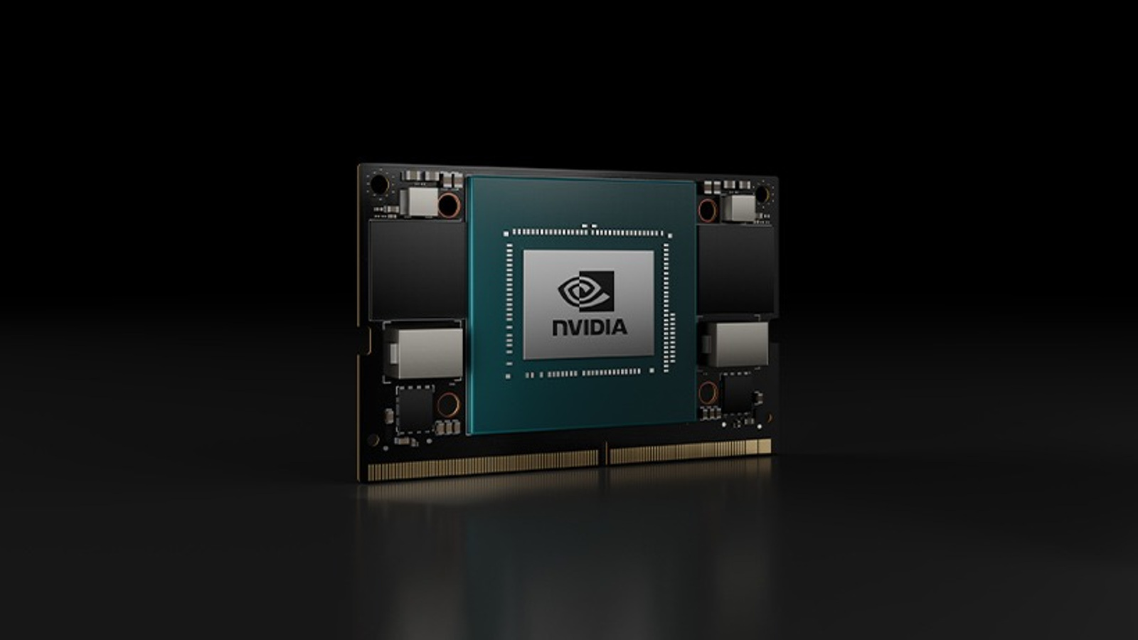
Architecture, materials & specificationsArchitecture options, material requirements and integration constraints
Architecture options
Integration format and control architecture are separate choices. A robot can combine a compute module with dedicated joint controllers.
| Approach | Mechanism | Advantages | Trade-offs |
|---|---|---|---|
| Compute module | Processor and memory connect to a carrier board designed for the robot. | Lets connectors, dimensions and cooling fit the body. | Requires carrier-board design, power integration and thermal validation. |
| Developer kit | A ready-made board packages the module with evaluation hardware. | Speeds software development and sensor testing. | Size, connectors and cooling may be unsuitable for a finished robot. |
| Separate real-time controllers | Dedicated controllers handle time-critical motor commands. | Keeps joint control cycles separate from variable AI workloads. | Adds communication, timing and fault-handling work between controllers. |
Specifications & operating limits
TOPS measures arithmetic throughput under specified conditions. Memory capacity limits what can fit, while bandwidth affects data movement. Workload and power setting determine the resulting latency.
Materials & constraints
- Semiconductor packages
- Provide processing, memory and power management.
- Copper PCB traces
- Connect the components and carry electrical signals.
- Thermal interfaces & heatsinks
- Transfer heat from the processor into the cooling system.
Dependencies & engineering limits
- Memory supply & module lifetime
- A compute module depends on memory, storage and power-management parts with their own lifecycles. Replacing a discontinued part can require board changes, software updates and system testing.
- AI compute & motor control
- AI processors handle perception and planning; real-time controllers regulate motion using current and position feedback. Controller count depends on the architecture: TI’s TIDA-010992 reference design controls six hand motors with one C2000 MCU. This is a reference-board configuration. Integrated actuators
- Power & cooling & sustained speed
- When temperature or power limits are reached, a processor may reduce its clock speed. Available cooling sets the sustainable workload inside the robot. Batteries & power
- Board integration & testing
- A module still needs suitable power rails, data interfaces and cooling. Concurrent sensors and workloads share bandwidth, power and cooling, so their combined behaviour can differ from isolated benchmarks.
- Model size & memory demand
- Memory holds both the model and its working data. Data transfer can limit throughput before the processor reaches its arithmetic capacity.
- Communication & control timing
- EtherCAT, CAN-FD and Ethernet interfaces serve different control architectures. Protocol support, bus load and command/feedback timing determine the delay between the controller and joints. Integrated actuators
Manufacturing & assembly
Parts & processes
No matching parts or examples.
Representative industrial route. Repeated wafer-processing cycles produce processor and memory chips. Packaged chips, boards, power and cooling form the computer that runs robot workloads.
Chips
Boards
Integration / calibration · Representative route. Connect Tech’s Forge manual provides the integration example.
Related parts & processes 6
Manufacturing · Representative route. Fabrication cycles repeat across many layers before wafer testing, die separation and packaging.
Related parts & processes 3
Manufacturing · Representative route. A conventional multilayer-board route feeding carrier assembly; fabrication capabilities are separate from chip manufacture.
Related parts & processes 1
Assembly · Representative route. A populated carrier needs a complete component kit, compatible assembly data and inspection before module installation. Eurocircuits provides the process example, not a claimed robot supplier.
Related parts & processes 7
Assembly · Representative route. Packaged chips and fabricated boards become modules and carriers before system integration.
Related parts & processes 7
Assembly · Representative route. Separate inputs converge into the supplied component.
Related parts & processes 5
Processors run perception, planning and learned workloads.
Production step for Processor & accelerator: Wafer test, packaging & final test.
Used in Compute module: Processor & accelerator.
Assembly input to Robot computer: Processor & accelerator.
Processor & accelerator
Processors run perception, planning and learned workloads.
System response time includes data transfer, processing and control delays.
Inputs & supporting parts
Wafer testing, die separation, package interconnection and final testing turn fabricated dies into packaged chips.
Where this fits
A module packages core compute functions for integration into a larger system.
Compute modules, carrier boards, storage, power delivery, cooling and peripheral interfaces form the robot computer.
Sources & technical scope
Illustrative images of generic materials and components.
This step
Related references
Models, intermediate results and software need memory and storage.
Used in Compute module: Memory & storage.
Assembly input to Robot computer: Memory & storage.
Memory & storage
Models, intermediate results and software need memory and storage.
Capacity and data movement can constrain a workload before arithmetic throughput.
Where this fits
A module packages core compute functions for integration into a larger system.
Compute modules, carrier boards, storage, power delivery, cooling and peripheral interfaces form the robot computer.
Sources & technical scope
Illustrative images of generic materials and components.
This step
Related references
A module packages core compute functions for integration into a larger system.
Used in Compute module: Memory & storage.
Used in Compute module: Processor & accelerator.
Assembly input to Board connector & mounting hardware: Compute module.
This step
Related references
Compute module
A module packages core compute functions for integration into a larger system.
Module interfaces and supported software constrain interchangeability.
Inputs & supporting parts
Models, intermediate results and software need memory and storage.
Processors run perception, planning and learned workloads.
Where this fits
The Forge carrier seats a Jetson AGX Orin module on a board-to-board connector.
Sources & technical scope
Illustrative images of generic materials and components.
This step
Related references
Carrier electronics connect power, sensors and other controllers.
Production step for Carrier & interfaces: Assembly inspection.
Assembly input to Board connector & mounting hardware: Carrier & interfaces.
Assembly input to Robot computer: Carrier & interfaces.
This step
Carrier & interfaces
Carrier electronics connect power, sensors and other controllers.
Concurrent inputs share interface bandwidth and power resources.
Inputs & supporting parts
Optical checks compare the populated board with the intended assembly.
Where this fits
The Forge carrier seats a Jetson AGX Orin module on a board-to-board connector.
Compute modules, carrier boards, storage, power delivery, cooling and peripheral interfaces form the robot computer.
Examples from industry 1
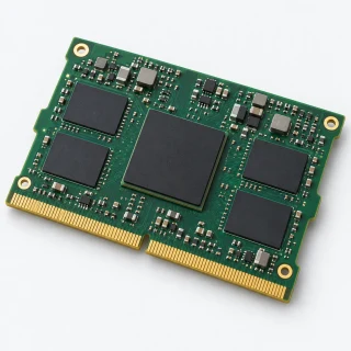 Generic
Forge is a carrier for NVIDIA Jetson AGX Orin modules, providing system interfaces around the compute module. Connect Tech lists carrier and integrated-assembly variants.
Sources & technical scope
Illustrative images of generic materials and components.
This step
Related references
The assembled system runs its workloads within available power and thermal limits.
Supporting dependency for Onboard workloads: Heat path & cooling.
Supporting dependency for Onboard workloads: Power delivery.
Supporting dependency for Onboard workloads: Real-time motor control.
Onboard workloads
The assembled system runs its workloads within available power and thermal limits.
Sustained performance depends on concurrent workloads, power delivery and cooling.
Inputs & supporting parts
Heat spreaders, cooling and enclosure conditions determine heat removal.
The system needs stable power for its configured operating modes.
Motor controllers use current and position feedback to regulate motion, alongside the AI processor’s perception and planning work.
Sources & technical scope
Illustrative images of generic materials and components.
This step
Link to this detailThe cooling system removes heat during sustained workloads. Thermal limits can reduce operating clocks and processing throughput.
Design alternative for Heat path & cooling: Thermal transfer plate.
Supporting dependency for Onboard workloads: Heat path & cooling.
Assembly input to Board connector & mounting hardware: Heat path & cooling.
Assembly input to Robot computer: Heat path & cooling.
This step
Heat path & cooling
Structure & materials →Heat spreaders, cooling and enclosure conditions determine heat removal.
Thermal limits can reduce operating clocks.
Inputs & supporting parts
A transfer plate moves heat out of the module toward the system’s cooling arrangement.
Where this fits
The assembled system runs its workloads within available power and thermal limits.
The Forge carrier seats a Jetson AGX Orin module on a board-to-board connector.
Compute modules, carrier boards, storage, power delivery, cooling and peripheral interfaces form the robot computer.
Sources & technical scope
Illustrative images of generic materials and components.
This step
Related references
The system needs stable power for its configured operating modes.
Supporting dependency for Onboard workloads: Power delivery.
Supporting dependency for Concurrent-load & thermal test: Power delivery.
Assembly input to Robot computer: Power delivery.
Power delivery
Batteries & power →The system needs stable power for its configured operating modes.
Module power budgets also affect battery and cooling choices.
Where this fits
The assembled system runs its workloads within available power and thermal limits.
Concurrent tests exercise compute, storage and attached peripherals together.
Compute modules, carrier boards, storage, power delivery, cooling and peripheral interfaces form the robot computer.
Sources & technical scope
Illustrative images of generic materials and components.
This step
Related references
Motor controllers use current and position feedback to regulate motion, alongside the AI processor’s perception and planning work.
Supporting dependency for Onboard workloads: Real-time motor control.
Real-time motor control
Integrated actuators →Motor controllers use current and position feedback to regulate motion, alongside the AI processor’s perception and planning work.
TI’s TIDA-010992 hand reference design controls six motors with one MCU; controller count is architecture-dependent.
Where this fits
The assembled system runs its workloads within available power and thermal limits.
Sources & technical scope
Illustrative images of generic materials and components.
This step
Link to this detailA transfer plate moves heat out of the module toward the system’s cooling arrangement.
Design alternative for Heat path & cooling: Thermal transfer plate.
Assembly input to Board connector & mounting hardware: Thermal transfer plate.
Thermal transfer plate
A transfer plate moves heat out of the module toward the system’s cooling arrangement.
The plate connects to a heatsink or other cooling arrangement that removes the transferred heat.
Where this fits
Heat spreaders, cooling and enclosure conditions determine heat removal.
The Forge carrier seats a Jetson AGX Orin module on a board-to-board connector.
Examples from industry 1
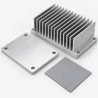 Generic
Forge uses separate thermal transfer plates for the module and 10G Ethernet hardware. Both need additional heat removal.
Sources & technical scope
Illustrative images of generic materials and components.
Related references
Forge is a carrier for NVIDIA Jetson AGX Orin modules, providing system interfaces around the compute module. Connect Tech lists carrier and integrated-assembly variants.
Connect Tech · Forge for Jetson AGX Orin
Manufacturer offeringForge is a carrier for NVIDIA Jetson AGX Orin modules, providing system interfaces around the compute module. Connect Tech lists carrier and integrated-assembly variants.
Carrier compatibility is module-specific. Camera interfaces, software support and power requirements must fit the intended robot configuration.
Where this fits
Carrier electronics connect power, sensors and other controllers.
Sources & technical scope
Illustrative images of generic materials and components.
Related references
Forge uses separate thermal transfer plates for the module and 10G Ethernet hardware. Both need additional heat removal.
Connect Tech · Forge thermal design
Documented architectureForge uses separate thermal transfer plates for the module and 10G Ethernet hardware. Both need additional heat removal.
Enclosure and cooling design determine how heat leaves the installed system.
Where this fits
A transfer plate moves heat out of the module toward the system’s cooling arrangement.
Sources & technical scope
Illustrative images of generic materials and components.
Link to this detailChip fabrication begins with a smooth silicon wafer on which many dies are built.
Material input to Thin-film deposition: Silicon wafer.
Silicon wafer
Chip fabrication begins with a smooth silicon wafer on which many dies are built.
Where this fits
Conducting, insulating and semiconducting films are deposited for device structures and interconnects.
Sources & technical scope
Illustrative images of generic materials and components.
Link to this detailConducting, insulating and semiconducting films are deposited for device structures and interconnects.
Material input to Thin-film deposition: Silicon wafer.
Sequence: Thin-film deposition → Resist, exposure & etching.
Thin-film deposition
Conducting, insulating and semiconducting films are deposited for device structures and interconnects.
Deposition repeats as successive device and interconnect layers are formed.
Inputs & supporting parts
Chip fabrication begins with a smooth silicon wafer on which many dies are built.
Where this fits
Photoresist and lithography define patterns; etching transfers selected features into the stack.
Sources & technical scope
Illustrative images of generic materials and components.
Link to this detailRepeated lithography and etching define the chip’s patterned layers. Wafer fabrication precedes chip packaging.
Sequence: Thin-film deposition → Resist, exposure & etching.
Material input to Resist, exposure & etching: Masks, resist & process chemicals.
Supporting dependency for Resist, exposure & etching: Cleanroom & layer alignment.
Sequence: Resist, exposure & etching → Doping & resist removal.
Related references
Resist, exposure & etching
Photoresist and lithography define patterns; etching transfers selected features into the stack.
Lithography and etching are different process capabilities.
Inputs & supporting parts
Conducting, insulating and semiconducting films are deposited for device structures and interconnects.
Patterning depends on reticles, light-sensitive resist and controlled processing materials.
Particle control limits contamination; alignment registers features across successive layers.
Where this fits
Ion implantation alters selected silicon regions to form electronic devices.
Sources & technical scope
Illustrative images of generic materials and components.
Related references
Wafer testing, die separation, package interconnection and final testing turn fabricated dies into packaged chips. Semiconductor packaging is a separate production dependency from wafer fabrication.
Sequence: Doping & resist removal → Wafer test, packaging & final test.
Production step for Processor & accelerator: Wafer test, packaging & final test.
Related references
Wafer test, packaging & final test
Wafer testing, die separation, package interconnection and final testing turn fabricated dies into packaged chips. Semiconductor packaging is a separate production dependency from wafer fabrication.
Packaging is a separate dependency from fabrication of the transistor layers.
Inputs & supporting parts
Ion implantation alters selected silicon regions to form electronic devices.
Where this fits
Processors run perception, planning and learned workloads.
Sources & technical scope
Illustrative images of generic materials and components.
Related references
Patterning depends on reticles, light-sensitive resist and controlled processing materials.
Material input to Resist, exposure & etching: Masks, resist & process chemicals.
Masks, resist & process chemicals
Patterning depends on reticles, light-sensitive resist and controlled processing materials.
Where this fits
Photoresist and lithography define patterns; etching transfers selected features into the stack.
Sources & technical scope
Illustrative images of generic materials and components.
Link to this detailParticle control limits contamination; alignment registers features across successive layers.
Supporting dependency for Resist, exposure & etching: Cleanroom & layer alignment.
Related references
Cleanroom & layer alignment
Particle control limits contamination; alignment registers features across successive layers.
Where this fits
Photoresist and lithography define patterns; etching transfers selected features into the stack.
Sources & technical scope
Illustrative images of generic materials and components.
Related references
The Forge carrier seats a Jetson AGX Orin module on a board-to-board connector. Mounting hardware retains the module while its heatspreader mates to the cooling assembly.
Assembly input to Board connector & mounting hardware: Compute module.
Assembly input to Board connector & mounting hardware: Carrier & interfaces.
Assembly input to Board connector & mounting hardware: Heat path & cooling.
Assembly input to Board connector & mounting hardware: Thermal transfer plate.
Sequence: Board connector & mounting hardware → Storage & peripheral wiring.
Board connector & mounting hardware
The Forge carrier seats a Jetson AGX Orin module on a board-to-board connector. Mounting hardware retains the module while its heatspreader mates to the cooling assembly.
Inputs & supporting parts
A module packages core compute functions for integration into a larger system.
Carrier electronics connect power, sensors and other controllers.
Heat spreaders, cooling and enclosure conditions determine heat removal.
A transfer plate moves heat out of the module toward the system’s cooling arrangement.
Where this fits
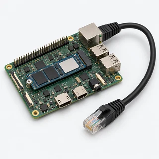
Storage, expansion modules and data cables connect the computer to peripherals.
Sources & technical scope
Illustrative images of generic materials and components.
Related references
Storage, expansion modules and data cables connect the computer to peripherals. Supported camera, Ethernet, USB and CAN interfaces depend on the carrier design.
Sequence: Board connector & mounting hardware → Storage & peripheral wiring.
Sequence: Storage & peripheral wiring → Boot image & board configuration.
Storage & peripheral wiring
Storage, expansion modules and data cables connect the computer to peripherals. Supported camera, Ethernet, USB and CAN interfaces depend on the carrier design.
Inputs & supporting parts
The Forge carrier seats a Jetson AGX Orin module on a board-to-board connector.
Where this fits
The recovery USB connection loads system software onto the module.
Sources & technical scope
Illustrative images of generic materials and components.
Link to this detailThe recovery USB connection loads system software onto the module. The board configuration and drivers enable the carrier’s connected devices.
Sequence: Storage & peripheral wiring → Boot image & board configuration.
Sequence: Computer assembly → Boot image & board configuration.
Checks on Boot image & board configuration: Concurrent-load & thermal test.
Sequence: Boot image & board configuration → Concurrent-load & thermal test.
Boot image & board configuration
The recovery USB connection loads system software onto the module. The board configuration and drivers enable the carrier’s connected devices.
Inputs & supporting parts
Storage, expansion modules and data cables connect the computer to peripherals.
Packaged chips and bare boards become populated modules and carriers through soldering and inspection.
Where this fits
Concurrent tests exercise compute, storage and attached peripherals together.
Sources & technical scope
Illustrative images of generic materials and components.
Related references
Concurrent tests exercise compute, storage and attached peripherals together. The carrier’s system-power test combines camera and USB loads with CPU/GPU stress.
Checks on Boot image & board configuration: Concurrent-load & thermal test.
Supporting dependency for Concurrent-load & thermal test: Power delivery.
Sequence: Boot image & board configuration → Concurrent-load & thermal test.
Sequence: Computer assembly → Concurrent-load & thermal test.
Production step for Robot computer: Concurrent-load & thermal test.
Concurrent-load & thermal test
Concurrent tests exercise compute, storage and attached peripherals together. The carrier’s system-power test combines camera and USB loads with CPU/GPU stress.
The input supply powers attached peripherals as well as the compute module.
Inputs & supporting parts
The recovery USB connection loads system software onto the module.
The system needs stable power for its configured operating modes.
Packaged chips and bare boards become populated modules and carriers through soldering and inspection.
Where this fits
Compute modules, carrier boards, storage, power delivery, cooling and peripheral interfaces form the robot computer.
Sources & technical scope
Illustrative images of generic materials and components.
Related references
Ion implantation alters selected silicon regions to form electronic devices. Resist is removed after processing; patterning recurs for successive layers.
Sequence: Resist, exposure & etching → Doping & resist removal.
Sequence: Doping & resist removal → Wafer test, packaging & final test.
Doping & resist removal
Ion implantation alters selected silicon regions to form electronic devices. Resist is removed after processing; patterning recurs for successive layers.
Inputs & supporting parts
Photoresist and lithography define patterns; etching transfers selected features into the stack.
Where this fits
Wafer testing, die separation, package interconnection and final testing turn fabricated dies into packaged chips.
Sources & technical scope
Illustrative images of generic materials and components.
Link to this detailLaminate cores, prepreg and copper foil form a multilayer board. Eurocircuits records material identity and thickness in the job history.
Material input to Inner-layer patterning & inspection: Laminate, prepreg & copper.
Laminate, prepreg & copper
Laminate cores, prepreg and copper foil form a multilayer board. Eurocircuits records material identity and thickness in the job history.
Material grade and copper thickness are specified inputs to the fabrication order.
Where this fits
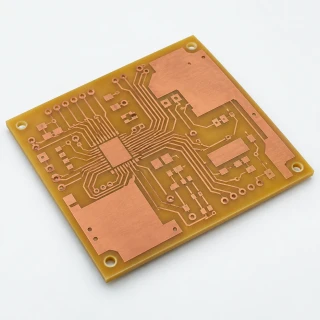
Etching defines copper tracks.
Sources & technical scope
Illustrative images of generic materials and components.
Link to this detailEtching defines copper tracks. Optical inspection compares inner layers with design data before bonding.
Material input to Inner-layer patterning & inspection: Laminate, prepreg & copper.
Sequence: Inner-layer patterning & inspection → Multilayer bonding.
Inner-layer patterning & inspection
Etching defines copper tracks. Optical inspection compares inner layers with design data before bonding.
Track width, spacing and registration constrain fabrication.
Inputs & supporting parts
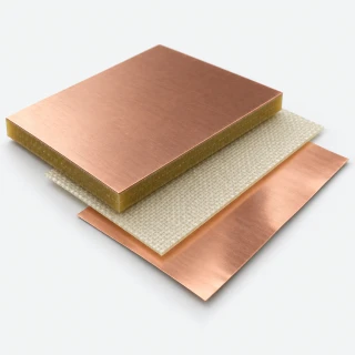
Laminate cores, prepreg and copper foil form a multilayer board.
Where this fits

Prepreg bonds the patterned layers into a stack; panel thickness is checked afterward.
Sources & technical scope
Illustrative images of generic materials and components.
Link to this detailPrepreg bonds the patterned layers into a stack; panel thickness is checked afterward.
Sequence: Inner-layer patterning & inspection → Multilayer bonding.
Sequence: Multilayer bonding → Drilling & through-hole plating.
Multilayer bonding
Prepreg bonds the patterned layers into a stack; panel thickness is checked afterward.
Inputs & supporting parts
Etching defines copper tracks.
Where this fits
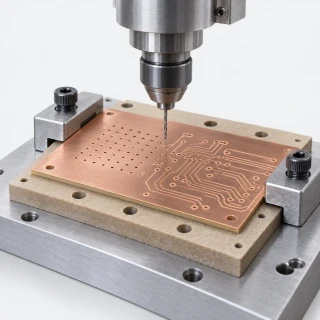
Drilled holes receive conductive preparation and copper plating to connect layers.
Sources & technical scope
Illustrative images of generic materials and components.
Link to this detailDrilled holes receive conductive preparation and copper plating to connect layers.
Sequence: Multilayer bonding → Drilling & through-hole plating.
Sequence: Drilling & through-hole plating → Outer copper, mask & finish.
Checks on Drilling & through-hole plating: Microsection test coupons.
Related references
Drilling & through-hole plating
Drilled holes receive conductive preparation and copper plating to connect layers.
Hole registration and deposited copper thickness require separate checks.
Inputs & supporting parts
Prepreg bonds the patterned layers into a stack; panel thickness is checked afterward.
Where this fits
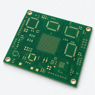
Outer tracks are etched, soldermask aligned and exposed copper given a surface finish.
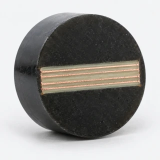
A sample is cut, embedded, ground and polished to inspect internal layers and plated holes.
Sources & technical scope
Illustrative images of generic materials and components.
Related references
Outer tracks are etched, soldermask aligned and exposed copper given a surface finish.
Sequence: Drilling & through-hole plating → Outer copper, mask & finish.
Production step for Tested bare board: Outer copper, mask & finish.
Outer copper, mask & finish
Outer tracks are etched, soldermask aligned and exposed copper given a surface finish.
Inputs & supporting parts
Drilled holes receive conductive preparation and copper plating to connect layers.
Where this fits
Electrical testing checks opens and shorts against a netlist; profiling defines the board outline.
Sources & technical scope
Illustrative images of generic materials and components.
Link to this detailElectrical testing checks opens and shorts against a netlist; profiling defines the board outline.
Production step for Tested bare board: Outer copper, mask & finish.
Assembly input to Solder paste & deposit inspection: Tested bare board.
Sequence: Tested bare board → Computer assembly.
Tested bare board
Electrical testing checks opens and shorts against a netlist; profiling defines the board outline.
This is a fabrication output, before component population and system testing.
Inputs & supporting parts
Outer tracks are etched, soldermask aligned and exposed copper given a surface finish.
Where this fits
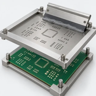
Stencil printing or jetting deposits solder paste.
Packaged chips and bare boards become populated modules and carriers through soldering and inspection.
Sources & technical scope
Illustrative images of generic materials and components.
Related references
A sample is cut, embedded, ground and polished to inspect internal layers and plated holes.
Checks on Drilling & through-hole plating: Microsection test coupons.
Related references
Microsection test coupons
A sample is cut, embedded, ground and polished to inspect internal layers and plated holes.
Destructive sampling checks bonding, registration and plating quality. It cannot be performed on every delivered board.
Inputs & supporting parts
Drilled holes receive conductive preparation and copper plating to connect layers.
Sources & technical scope
Illustrative images of generic materials and components.
Related references
Eurocircuits checks part numbers, quantities and markings, then groups parts, boards and stencils by manufacturing order.
Supporting dependency for Component receipt & complete kit: Moisture-sensitive component storage.
Sequence: Component receipt & complete kit → Solder paste & deposit inspection.
Component receipt & complete kit
Eurocircuits checks part numbers, quantities and markings, then groups parts, boards and stencils by manufacturing order.
The job moves to kitting when all components are available. Moisture-sensitive packages remain sealed until assembly starts.
Inputs & supporting parts
Moisture sensitivity affects when sealed component packaging can be opened.
Where this fits
Stencil printing or jetting deposits solder paste.
Sources & technical scope
Illustrative images of generic materials and components.
Related references
The bill of materials identifies manufacturer part numbers; placement data locates parts on the board.
Supporting dependency for Component placement: BOM, footprints & placement data.
BOM, footprints & placement data
The bill of materials identifies manufacturer part numbers; placement data locates parts on the board.
Assembly review checks package fit, polarity and special mounting or reflow requirements. A replacement part must pass those checks.
Where this fits
Feeders supply parts to pick-and-place equipment.
Sources & technical scope
Illustrative images of generic materials and components.
Link to this detailStencil printing or jetting deposits solder paste. Inspection measures the deposits before component placement.
Sequence: Component receipt & complete kit → Solder paste & deposit inspection.
Assembly input to Solder paste & deposit inspection: Tested bare board.
Production equipment for Solder paste & deposit inspection: Solder-paste stencil or jetter.
Sequence: Solder paste & deposit inspection → Component placement.
Solder paste & deposit inspection
Stencil printing or jetting deposits solder paste. Inspection measures the deposits before component placement.
Inputs & supporting parts
Eurocircuits checks part numbers, quantities and markings, then groups parts, boards and stencils by manufacturing order.
Electrical testing checks opens and shorts against a netlist; profiling defines the board outline.
A board-specific stencil or programmed jetter controls paste deposition.
Where this fits
Feeders supply parts to pick-and-place equipment.
Sources & technical scope
Illustrative images of generic materials and components.
Related references
Feeders supply parts to pick-and-place equipment.
Sequence: Solder paste & deposit inspection → Component placement.
Supporting dependency for Component placement: BOM, footprints & placement data.
Production equipment for Component placement: Pick-and-place equipment.
Sequence: Component placement → Reflow soldering.
Component placement
Feeders supply parts to pick-and-place equipment.
Package dimensions and orientation must match the prepared assembly data.
Inputs & supporting parts
Stencil printing or jetting deposits solder paste.
The bill of materials identifies manufacturer part numbers; placement data locates parts on the board.
Placement heads and feeders handle the specified component packages.
Where this fits
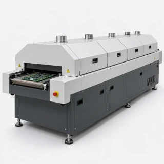
A controlled heating and cooling profile forms the surface-mount solder joints.
Sources & technical scope
Illustrative images of generic materials and components.
Link to this detailA controlled heating and cooling profile forms the surface-mount solder joints.
Sequence: Component placement → Reflow soldering.
Production equipment for Reflow soldering: Reflow oven.
Checks on Reflow soldering: Assembly inspection.
Checks on Reflow soldering: Hidden-joint X-ray inspection.
Related references
Reflow soldering
A controlled heating and cooling profile forms the surface-mount solder joints.
Through-hole components can require a separate selective or manual soldering operation.
Inputs & supporting parts
Feeders supply parts to pick-and-place equipment.
The oven provides preheat, soak, reflow and cooling stages.
Where this fits
Optical checks compare the populated board with the intended assembly.
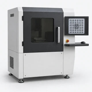
X-ray inspection reveals solder joints beneath BGA, LGA and QFN packages, including voids and other internal defects.
Sources & technical scope
Illustrative images of generic materials and components.
Related references
Optical checks compare the populated board with the intended assembly.
Checks on Reflow soldering: Assembly inspection.
Production step for Carrier & interfaces: Assembly inspection.
Assembly inspection
Optical checks compare the populated board with the intended assembly.
Hidden joints need an additional inspection method.
Inputs & supporting parts
A controlled heating and cooling profile forms the surface-mount solder joints.
Where this fits
Carrier electronics connect power, sensors and other controllers.
Sources & technical scope
Illustrative images of generic materials and components.
Related references
X-ray inspection reveals solder joints beneath BGA, LGA and QFN packages, including voids and other internal defects.
Checks on Reflow soldering: Hidden-joint X-ray inspection.
Related references
Hidden-joint X-ray inspection
X-ray inspection reveals solder joints beneath BGA, LGA and QFN packages, including voids and other internal defects.
Eurocircuits describes first-board and sampled inspection because the process takes time; X-ray capability does not mean every board is X-rayed.
Inputs & supporting parts
A controlled heating and cooling profile forms the surface-mount solder joints.
Sources & technical scope
Illustrative images of generic materials and components.
Related references
Moisture sensitivity affects when sealed component packaging can be opened.
Supporting dependency for Component receipt & complete kit: Moisture-sensitive component storage.
Moisture-sensitive component storage
Moisture sensitivity affects when sealed component packaging can be opened.
Receipt, storage and production release are part of the assembly dependency, alongside the component itself.
Where this fits
Eurocircuits checks part numbers, quantities and markings, then groups parts, boards and stencils by manufacturing order.
Sources & technical scope
Illustrative images of generic materials and components.
Link to this detailA board-specific stencil or programmed jetter controls paste deposition.
Production equipment for Solder paste & deposit inspection: Solder-paste stencil or jetter.
Solder-paste stencil or jetter
A board-specific stencil or programmed jetter controls paste deposition.
Where this fits
Stencil printing or jetting deposits solder paste.
Sources & technical scope
Illustrative images of generic materials and components.
Link to this detailPlacement heads and feeders handle the specified component packages.
Production equipment for Component placement: Pick-and-place equipment.
Pick-and-place equipment
Placement heads and feeders handle the specified component packages.
Equipment for this step →Where this fits
Feeders supply parts to pick-and-place equipment.
Sources & technical scope
Illustrative images of generic materials and components.
Link to this detailThe oven provides preheat, soak, reflow and cooling stages.
Production equipment for Reflow soldering: Reflow oven.
Reflow oven
The oven provides preheat, soak, reflow and cooling stages.
Where this fits
A controlled heating and cooling profile forms the surface-mount solder joints.
Sources & technical scope
Illustrative images of generic materials and components.
Link to this detailPackaged chips and bare boards become populated modules and carriers through soldering and inspection. Power delivery, storage, connectors and cooling complete the computer assembly.
Sequence: Tested bare board → Computer assembly.
Sequence: Computer assembly → Boot image & board configuration.
Sequence: Computer assembly → Concurrent-load & thermal test.
Computer assembly
Packaged chips and bare boards become populated modules and carriers through soldering and inspection. Power delivery, storage, connectors and cooling complete the computer assembly.
Inputs & supporting parts
Electrical testing checks opens and shorts against a netlist; profiling defines the board outline.
Where this fits
The recovery USB connection loads system software onto the module.
Concurrent tests exercise compute, storage and attached peripherals together.
Sources & technical scope
Illustrative images of generic materials and components.
This step
Related references
Compute modules, carrier boards, storage, power delivery, cooling and peripheral interfaces form the robot computer. Software support depends on the selected module and carrier.
Production step for Robot computer: Concurrent-load & thermal test.
Assembly input to Robot computer: Processor & accelerator.
Assembly input to Robot computer: Memory & storage.
Assembly input to Robot computer: Carrier & interfaces.
Assembly input to Robot computer: Power delivery.
Assembly input to Robot computer: Heat path & cooling.
This step
Robot computer
Compute modules, carrier boards, storage, power delivery, cooling and peripheral interfaces form the robot computer. Software support depends on the selected module and carrier.
Inputs & supporting parts
Concurrent tests exercise compute, storage and attached peripherals together.
Processors run perception, planning and learned workloads.
Models, intermediate results and software need memory and storage.
Carrier electronics connect power, sensors and other controllers.
The system needs stable power for its configured operating modes.
Heat spreaders, cooling and enclosure conditions determine heat removal.
Sources & technical scope
Illustrative images of generic materials and components.
This step
Related references
Production equipment
- DISCOWafer dicing equipment
Blade and laser systems separate semiconductor wafers into individual dies before package assembly.
Die separation →JapanSources
Cameras and compute · semiconductor dies
DISCO · precision processing equipment - Hanwha SemitechSMT component-placement machines
Chip mounters place electronic components on circuit boards before soldering. The populated boards form motor drives and onboard computers.
PCB component placement →South KoreaSources
Motor drives and compute · populated circuit boards
Hanwha Semitech · SMT equipmentHanwha · Semitech name change - Hanwha SemitechDie and flip-chip bonders
Die and flip-chip bonders attach semiconductor dies during packaging, before packaged chips are assembled onto compute boards.
Chip packaging →South KoreaSources
Onboard compute · semiconductor packages
Hanwha Semitech · semiconductor equipment - EV GroupWafer bonding & alignment systems
Aligned wafer bonding joins sensor layers and seals MEMS structures. Fusion and hybrid bonding also connect layers in stacked image sensors and advanced semiconductor packages.
Wafer bonding →EuropeSources
IMUs, image sensors and compute · bonded wafers and device layers
EV Group · wafer bonding technologies and systems
Market context
Jetson production-module pricing

US$999Orin NX 16GB · module · 1,000+ units
US$2,999AGX Orin 64GB · module · 1,000+ units
US$4,999Thor T5000 · module · 1,000+ units
A dated benchmark for onboard compute procurement. Module prices exclude the rest of a robot computer, including its carrier, cooling and enclosure.
ANYbotics

Zollner manufactures ANYmal’s PCBs, pre-assembles modules and completes robot assembly in Hombrechtikon, Switzerland. It also handles purchasing for more than 400 components, with specifications updated between production batches.
Jetson
NVIDIA lists Orin NX and commercial AGX Orin modules as available through January 2032, Thor T5000 through August 2035 and Thor T4000 through January 2036.
Unitree
Go2 EDU adds a depth camera and supports a separate high-compute module, including Orin options. The standard onboard eight-core CPU remains a distinct computing layer.
Companies
Browse components →NVIDIASupply connection · UnitreeIntelSupply connection · AddverbFuzhou Rockchip ElectronicsSupply connection · Pudu RoboticsANYboticselectronics and final assembly at ZollnerEspressif SystemsSupply connection · WaveshareRaspberry PiSupply connection · SuperDroid RobotsUnitreeperception and compute by configuration
Explore documented supply relationships →



Batteries & power
Supplies energy to joints, sensors and computers. Cells store the energy; pack electronics monitor it and control charging and discharge.
Inside a battery pack
Cells store energy; interconnects, sensing and protection turn them into a managed pack. Open the layers to inspect each role.
Source & model scope
Illustrative cylindrical-cell pack. Cell count, interconnects and monitoring-board layout are schematic; the view does not define a voltage, series/parallel configuration or wiring plan. Original Korthos geometry.
Texas Instruments · mobile robot battery management · Model scope & reuseArchitecture, materials & specificationsArchitecture options, material requirements and integration constraints
Architecture options
Chemistry, cell format and pack servicing are separate decisions. Pack performance varies with load and temperature.
| Approach | Mechanism | Advantages | Trade-offs |
|---|---|---|---|
| LFP cells | Lithium iron phosphate is used as the cathode material. | Avoids nickel and cobalt in the cathode; generally offers good cycle life. | Typically stores less energy per kilogram than high-energy nickel-based cells. |
| Nickel-based cells | Cathodes such as NMC combine nickel with other metals. | Can store more energy within a limited pack mass. | Temperature, operating limits and protection remain critical; formulations differ. |
| Fixed pack | The pack stays installed while charging. | Avoids a frequently disconnected battery interface. | Charging takes the robot out of service unless the operating setup allows otherwise. |
| Swappable pack | A depleted pack is exchanged for a charged one. | Can shorten the interruption between work periods. | Needs durable connectors, accessible mounting and a safe replacement procedure. |
Specifications & operating limits
Watt-hours measure stored energy; watts measure the rate of use. Runtime is approximately usable energy divided by average power, with conversion losses and reserve included. Stored energy depends on both charge capacity and voltage.
Materials & constraints
- Graphite-based anodes
- Graphite stores lithium during charging. Some anodes include silicon to increase storage, but expansion and repeated cycling must be managed. Cell construction and operating limits determine how much capacity remains usable over time.
- LFP or nickel-based cathodes
- Lithium iron phosphate avoids nickel and cobalt; nickel-manganese-cobalt chemistries make different energy-density and thermal-management trade-offs. Pack construction, operating limits and protection also affect runtime, lifespan and safety.
- Electrolyte & porous separator
- Electrolyte transports lithium ions; the separator keeps the electrodes apart while allowing ion movement. Temperature and mechanical damage affect these layers; cell protection and pack structure are separate assembly requirements.
- Copper, aluminium & pack structure
- Current collectors and interconnects carry electrical current; the enclosure supports and protects cells. Conductors, cooling, protection electronics and housing all add mass beyond the cells themselves.
Dependencies & engineering limits
- Cells & usable pack energy
- In a series pack, one cell group can reach its discharge limit before the others. Balancing helps manage charge differences; it does not repair lost cell capacity.
- Pack assembly & testing
- Cell connections, temperature sensing and protection electronics form a coupled pack system. Connection resistance and protection settings matter alongside the cell’s advertised capacity.
- Joint demand & voltage drop
- Brief high-current movements can cause voltage drop and heating. Peak demand places different loads on the pack and power stage from average consumption. Integrated actuators
- Ageing & replacement
- Usable capacity and power capability change with age and operating conditions. Pack access, mounting and connectors affect how easily a worn pack can be replaced. Structure & materials
Manufacturing & assembly
Parts & processes
No matching parts or examples.
Representative industrial route. This wet-coated lithium-ion route turns electrode materials into sheets, then cells. Formed and checked cells join with protection electronics and mechanical supports to make a robot battery pack.
Cells
Assembly inputs
Assembly · Representative route. Cell assembly plus a documented TI protection-board example.
Related parts & processes 5
Manufacturing · Representative route. A wet-electrode lithium-ion process, before module assembly.
Related parts & processes 6
Assembly · Representative route. Cell manufacture finishes before the pack is assembled and tested.
Related parts & processes 6
Cells provide the pack’s underlying energy storage.
Production step for Cells: Formation & ageing.
Assembly input to Cell restraint & insulation: Cells.
Checks on Cells: Cell quality control.
Sequence: Cells → Pack integration.
Cells
Cells provide the pack’s underlying energy storage.
Cell chemistry and format are separate design choices.
Inputs & supporting parts
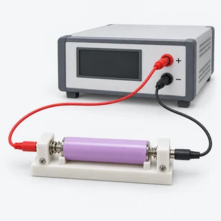
Initial cycling establishes the electrochemical interfaces.
Where this fits
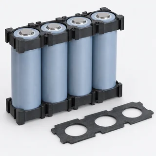
Cell-to-module assembly adds electrical contacts, thermal insulation and mechanical bracing.
Capacity, internal resistance, self-discharge and sealing checks grade cells before pack assembly.
Graded cells, interconnects, insulation and mechanical supports form the pack.
Examples from industry 1
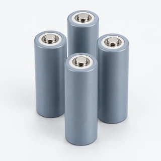 Generic
Molicel lists P45B as a cylindrical 21700 power cell, with cell-level capacity, current and energy-density specifications.
Sources & technical scope
Illustrative images of generic materials and components.
Related references
Electrical connections combine cells into the required pack arrangement.
Assembly input to Cell interconnects: Cell restraint & insulation.
Assembly input to Monitoring & balancing: Cell interconnects.
Cell interconnects
Electrical connections combine cells into the required pack arrangement.
Connection resistance affects heating and voltage loss.
Inputs & supporting parts
Cell-to-module assembly adds electrical contacts, thermal insulation and mechanical bracing.
Where this fits
Battery-management electronics measure cell conditions and can balance charge differences.
Sources & technical scope
Illustrative images of generic materials and components.
Related references
Battery-management electronics measure cell conditions and can balance charge differences.
Supporting dependency for Monitoring & balancing: Temperature sensing.
Design alternative for Monitoring & balancing: Cell-monitor & protection IC.
Assembly input to Monitoring & balancing: Cell interconnects.
Assembly input to Monitoring & balancing: Cell taps, shunt & thermistors.
Assembly input to Monitoring & balancing: Balancing resistors & switches.
Supporting dependency for Robot battery pack: Monitoring & balancing.
Assembly input to Disconnect MOSFETs & backup protection: Monitoring & balancing.
Monitoring & balancing
Battery-management electronics measure cell conditions and can balance charge differences.
Balancing corrects charge differences; cell ageing reduces capacity.
Inputs & supporting parts
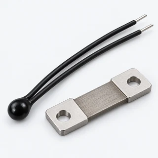
Temperature measurements inform pack monitoring and protection.
A pack-monitor IC measures cell conditions and supports protection and balancing.
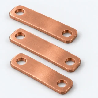
Electrical connections combine cells into the required pack arrangement.
Cell-voltage taps feed the monitor.
External resistors and MOSFETs discharge selected cells under monitor control.
Where this fits
The assembled pack supplies the robot’s movement and compute loads.
High-side MOSFETs interrupt charge or discharge.
Sources & technical scope
Illustrative images of generic materials and components.
Related references
Pack electronics monitor cell conditions and respond to configured fault and operating limits.
Used in Pack protection: Disconnect MOSFETs & backup protection.
Supporting dependency for Robot battery pack: Pack protection.
Pack protection
Protection controls respond to configured pack faults and limits.
Electronics, interconnects and sensors must work as a system.
Inputs & supporting parts
High-side MOSFETs interrupt charge or discharge.
Where this fits
The assembled pack supplies the robot’s movement and compute loads.
Sources & technical scope
Illustrative images of generic materials and components.
Related references
The assembled pack supplies the robot’s movement and compute loads.
Supporting dependency for Robot battery pack: Monitoring & balancing.
Supporting dependency for Robot battery pack: Pack protection.
Supporting dependency for Robot battery pack: Enclosure & service.
Supporting dependency for Robot battery pack: Measurement & protection tests.
Sequence: Measurement & protection tests → Robot battery pack.
Robot battery pack
The assembled pack supplies the robot’s movement and compute loads.
Stored energy and peak discharge capability are different measures.
Inputs & supporting parts
Battery-management electronics measure cell conditions and can balance charge differences.
Protection controls respond to configured pack faults and limits.
Mounting, access and connectors determine pack integration and replacement.
Electrical tests measure cell-voltage and pack-current accuracy, balancing, fault response and standby behaviour.
Sources & technical scope
Illustrative images of generic materials and components.
Related references
Lithium-ion cells combine electrode materials, electrolyte, separator and current collectors.
Material input to Electrode mixing: Electrodes & separator.
Electrodes & separator
Lithium-ion cells combine electrode materials, electrolyte, separator and current collectors.
Electrode material requirements vary by chemistry.
Where this fits
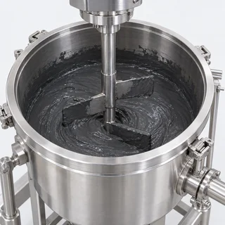
Each electrode has its own mixture of active material, binder and any conductive additives in a wet-coating route.
Sources & technical scope
Illustrative images of generic materials and components.
Related references
Temperature measurements inform pack monitoring and protection.
Supporting dependency for Monitoring & balancing: Temperature sensing.
Related references
Temperature sensing
Temperature measurements inform pack monitoring and protection.
High-current demand affects heat and voltage drop.
Where this fits
Battery-management electronics measure cell conditions and can balance charge differences.
Sources & technical scope
Illustrative images of generic materials and components.
Related references
Mounting, access and connectors determine pack integration and replacement.
Supporting dependency for Robot battery pack: Enclosure & service.
Related references
Enclosure & service
Structure & materials →Mounting, access and connectors determine pack integration and replacement.
A replaceable pack still needs a compatible electrical and mechanical interface.
Where this fits
The assembled pack supplies the robot’s movement and compute loads.
Sources & technical scope
Illustrative images of generic materials and components.
Related references
A pack-monitor IC measures cell conditions and supports protection and balancing.
Design alternative for Monitoring & balancing: Cell-monitor & protection IC.
Related references
Cell-monitor & protection IC
A pack-monitor IC measures cell conditions and supports protection and balancing.
Cell count, chemistry, external components and configured limits belong to the complete pack design.
Where this fits
Battery-management electronics measure cell conditions and can balance charge differences.
Examples from industry 1
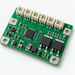 Generic
BQ76952 supports monitoring, protection and balancing in packs with 3–16 series-connected cells. TI documents support for Li-ion, Li-polymer and LiFePO4 chemistries.
Sources & technical scope
Illustrative images of generic materials and components.
Related references
Molicel lists P45B as a cylindrical 21700 power cell, with cell-level capacity, current and energy-density specifications.
This step
Molicel · INR-21700-P45B
Manufacturer offeringMolicel lists P45B as a cylindrical 21700 power cell, with cell-level capacity, current and energy-density specifications.
Cell specifications apply under their stated test conditions. Interconnects, protection, cooling and enclosure mass affect pack performance.
Where this fits
Cells provide the pack’s underlying energy storage.
Sources & technical scope
Illustrative images of generic materials and components.
This step
Link to this detailBQ76952 supports monitoring, protection and balancing in packs with 3–16 series-connected cells. TI documents support for Li-ion, Li-polymer and LiFePO4 chemistries.
Texas Instruments · BQ76952
Manufacturer offeringBQ76952 supports monitoring, protection and balancing in packs with 3–16 series-connected cells. TI documents support for Li-ion, Li-polymer and LiFePO4 chemistries.
Cell configuration, switching circuitry and protection settings define the pack’s operating limits.
Where this fits
A pack-monitor IC measures cell conditions and supports protection and balancing.
Sources & technical scope
Illustrative images of generic materials and components.
Link to this detailEach electrode has its own mixture of active material, binder and any conductive additives in a wet-coating route. Cathode and anode mixtures are prepared separately.
Material input to Electrode mixing: Electrodes & separator.
Material input to Electrode mixing: Cathode material chemistry.
Material input to Electrode mixing: Graphite anode material.
Sequence: Electrode mixing → Coating & drying.
Electrode mixing
Each electrode has its own mixture of active material, binder and any conductive additives in a wet-coating route. Cathode and anode mixtures are prepared separately.
Chemistry and solvent choices vary; dry-electrode routes are distinct.
Inputs & supporting parts
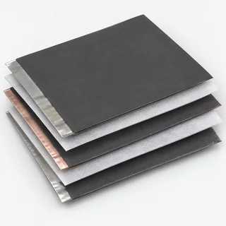
Lithium-ion cells combine electrode materials, electrolyte, separator and current collectors.
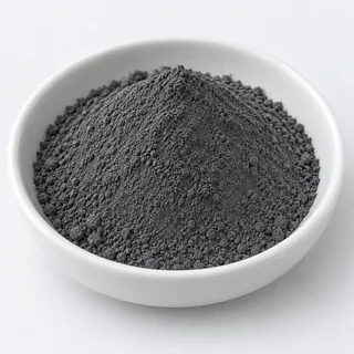
NMC uses nickel, manganese and cobalt alongside lithium; LFP uses lithium, iron and phosphate.
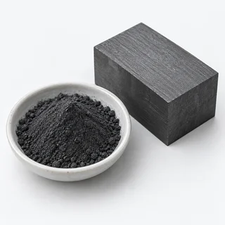
Graphite is a common lithium-ion anode material, with material requirements distinct from the cathode.
Where this fits
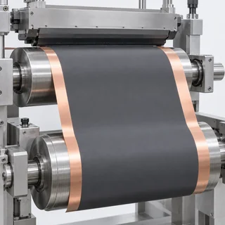
The mixture is applied to collector foil, then dried to remove solvent.
Sources & technical scope
Illustrative images of generic materials and components.
Related references
The mixture is applied to collector foil, then dried to remove solvent.
Sequence: Electrode mixing → Coating & drying.
Sequence: Coating & drying → Calendering & cutting.
Coating & drying
The mixture is applied to collector foil, then dried to remove solvent.
Drying conditions affect adhesion and electrode structure.
Inputs & supporting parts
Each electrode has its own mixture of active material, binder and any conductive additives in a wet-coating route.
Where this fits
Calendering compacts the coated electrodes; slitting and cutting prepare strips or sheets for cell assembly.
Sources & technical scope
Illustrative images of generic materials and components.
Related references
Calendering compacts the coated electrodes; slitting and cutting prepare strips or sheets for cell assembly. Vacuum drying removes residual moisture, either before assembly or through cell baking before electrolyte filling.
Sequence: Coating & drying → Calendering & cutting.
Assembly input to Stacking or winding: Calendering & cutting.
Calendering & cutting
Calendering compacts the coated electrodes; slitting and cutting prepare strips or sheets for cell assembly. Vacuum drying removes residual moisture, either before assembly or through cell baking before electrolyte filling.
Compaction is controlled to achieve the required electrode structure.
Inputs & supporting parts
The mixture is applied to collector foil, then dried to remove solvent.
Where this fits
Electrodes and separators form a wound or stacked assembly.
Sources & technical scope
Illustrative images of generic materials and components.
This step
Link to this detailStacking or winding assembles the electrodes and separator into the cell format. Further finishing completes the cell.
Assembly input to Stacking or winding: Calendering & cutting.
Material input to Stacking or winding: Collector foils & separator.
Sequence: Stacking or winding → Electrolyte filling & wetting.
Stacking or winding
Electrodes and separators form a wound or stacked assembly. Current-collector joining and pouch or can packaging create the cell structure before electrolyte filling.
Stacking and winding are alternative assembly arrangements.
Inputs & supporting parts
Calendering compacts the coated electrodes; slitting and cutting prepare strips or sheets for cell assembly.
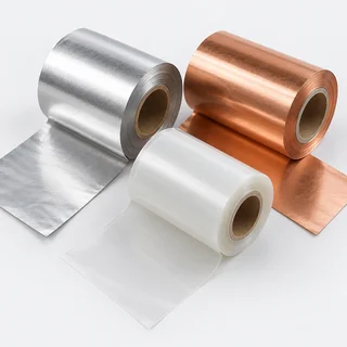
Conductive foils support the electrodes.
Where this fits
Electrolyte filling and wetting establish ionic contact through the porous electrodes and separator.
Sources & technical scope
Illustrative images of generic materials and components.
This step
Related references
Electrolyte filling and wetting establish ionic contact through the porous electrodes and separator. Closure and degassing stages depend on cell format and formation process.
Sequence: Stacking or winding → Electrolyte filling & wetting.
Sequence: Electrolyte filling & wetting → Formation & ageing.
Electrolyte filling & wetting
Electrolyte filling and wetting establish ionic contact through the porous electrodes and separator. Closure and degassing stages depend on cell format and formation process.
Uneven wetting can compromise subsequent formation.
Inputs & supporting parts
Electrodes and separators form a wound or stacked assembly.
Where this fits
Initial cycling establishes the electrochemical interfaces.
Sources & technical scope
Illustrative images of generic materials and components.
This step
Related references
Controlled initial cycling establishes electrochemical interfaces, followed by ageing and cell-quality checks.
Sequence: Electrolyte filling & wetting → Formation & ageing.
Production step for Cells: Formation & ageing.
Formation & ageing
Initial cycling establishes the electrochemical interfaces. Format-dependent degassing and final sealing are followed by ageing and grading.
Inputs & supporting parts
Electrolyte filling and wetting establish ionic contact through the porous electrodes and separator.
Where this fits
Cells provide the pack’s underlying energy storage.
Sources & technical scope
Illustrative images of generic materials and components.
This step
Related references
Capacity, internal resistance, self-discharge and sealing checks grade cells before pack assembly.
Checks on Cells: Cell quality control.
Cell quality control
Capacity, internal resistance, self-discharge and sealing checks grade cells before pack assembly.
This is distinct from pack monitoring, protection and system qualification.
Inputs & supporting parts
Cells provide the pack’s underlying energy storage.
Sources & technical scope
Illustrative images of generic materials and components.
This step
Link to this detailCell-to-module assembly adds electrical contacts, thermal insulation and mechanical bracing. The cell format determines the supporting module arrangement.
Assembly input to Cell restraint & insulation: Cells.
Assembly input to Cell interconnects: Cell restraint & insulation.
Cell restraint & insulation
Cell-to-module assembly adds electrical contacts, thermal insulation and mechanical bracing. The cell format determines the supporting module arrangement.
Inputs & supporting parts
Cells provide the pack’s underlying energy storage.
Where this fits
Electrical connections combine cells into the required pack arrangement.
Sources & technical scope
Illustrative images of generic materials and components.
Related references
Cell-voltage taps feed the monitor. A shunt measures pack current, while thermistors measure cell and switching-device temperatures.
Assembly input to Monitoring & balancing: Cell taps, shunt & thermistors.
Related references
Cell taps, shunt & thermistors
Cell-voltage taps feed the monitor. A shunt measures pack current, while thermistors measure cell and switching-device temperatures.
Where this fits
Battery-management electronics measure cell conditions and can balance charge differences.
Sources & technical scope
Illustrative images of generic materials and components.
Related references
External resistors and MOSFETs discharge selected cells under monitor control. The TI reference balances non-adjacent cells and checks voltage and temperature conditions.
Assembly input to Monitoring & balancing: Balancing resistors & switches.
Related references
Balancing resistors & switches
External resistors and MOSFETs discharge selected cells under monitor control. The TI reference balances non-adjacent cells and checks voltage and temperature conditions.
Where this fits
Battery-management electronics measure cell conditions and can balance charge differences.
Sources & technical scope
Illustrative images of generic materials and components.
Related references
The monitor detects a fault; power switches interrupt the current path. A separate protection channel can provide an additional response to excessive voltage or temperature.
Assembly input to Disconnect MOSFETs & backup protection: Monitoring & balancing.
Checks on Disconnect MOSFETs & backup protection: Measurement & protection tests.
Used in Pack protection: Disconnect MOSFETs & backup protection.
Disconnect MOSFETs & backup protection
High-side MOSFETs interrupt charge or discharge. TI’s design adds a separate voltage-and-temperature protector alongside the primary monitor.
Inputs & supporting parts
Battery-management electronics measure cell conditions and can balance charge differences.
Where this fits
Electrical tests measure cell-voltage and pack-current accuracy, balancing, fault response and standby behaviour.
Protection controls respond to configured pack faults and limits.
Sources & technical scope
Illustrative images of generic materials and components.
Related references
Electrical tests measure cell-voltage and pack-current accuracy, balancing, fault response and standby behaviour. Current calibration accounts for board offset and gain.
Checks on Disconnect MOSFETs & backup protection: Measurement & protection tests.
Sequence: Pack integration → Measurement & protection tests.
Supporting dependency for Robot battery pack: Measurement & protection tests.
Sequence: Measurement & protection tests → Robot battery pack.
Measurement & protection tests
Electrical tests measure cell-voltage and pack-current accuracy, balancing, fault response and standby behaviour. Current calibration accounts for board offset and gain.
Inputs & supporting parts
High-side MOSFETs interrupt charge or discharge.
Graded cells, interconnects, insulation and mechanical supports form the pack.
Where this fits
The assembled pack supplies the robot’s movement and compute loads.
Sources & technical scope
Illustrative images of generic materials and components.
Related references
Conductive foils support the electrodes. A porous separator keeps the electrodes apart while electrolyte carries ions through the cell.
Material input to Stacking or winding: Collector foils & separator.
Collector foils & separator
Conductive foils support the electrodes. A porous separator keeps the electrodes apart while electrolyte carries ions through the cell.
Where this fits
Electrodes and separators form a wound or stacked assembly.
Sources & technical scope
Illustrative images of generic materials and components.
Related references
NMC uses nickel, manganese and cobalt alongside lithium; LFP uses lithium, iron and phosphate.
Material input to Electrode mixing: Cathode material chemistry.
Related references
Cathode material chemistry
NMC uses nickel, manganese and cobalt alongside lithium; LFP uses lithium, iron and phosphate.
Nickel and cobalt are not universal lithium-ion battery requirements.
Where this fits
Each electrode has its own mixture of active material, binder and any conductive additives in a wet-coating route.
Sources & technical scope
Illustrative images of generic materials and components.
Related references
Graphite is a common lithium-ion anode material, with material requirements distinct from the cathode.
Material input to Electrode mixing: Graphite anode material.
Related references
Graphite anode material
Graphite is a common lithium-ion anode material, with material requirements distinct from the cathode.
The selected cell may use a different anode formulation.
Where this fits
Each electrode has its own mixture of active material, binder and any conductive additives in a wet-coating route.
Sources & technical scope
Illustrative images of generic materials and components.
Related references
Graded cells, interconnects, insulation and mechanical supports form the pack. Voltage and temperature sensors, protection electronics, power interfaces and an enclosure complete the assembly.
Sequence: Cells → Pack integration.
Sequence: Pack integration → Measurement & protection tests.
Pack integration
Graded cells, interconnects, insulation and mechanical supports form the pack. Voltage and temperature sensors, protection electronics, power interfaces and an enclosure complete the assembly.
Inputs & supporting parts
Cells provide the pack’s underlying energy storage.
Where this fits
Electrical tests measure cell-voltage and pack-current accuracy, balancing, fault response and standby behaviour.
Sources & technical scope
Illustrative images of generic materials and components.
This step
Link to this detailProduction equipment
- Hanwha MomentumBattery-electrode coaters and roll presses
Coaters deposit cathode and anode layers; roll presses compress the coated electrodes to a controlled thickness before cell assembly.
Electrode coating →South KoreaSources
Battery cells · coated and calendered electrodes
Hanwha Momentum · electrode processing - TRUMPFBattery interconnect laser welding
Laser welding joins copper and aluminium cell connectors and battery housings. Joint design and heat input must suit the cell format and conductor thickness.
Cell interconnects →EuropeSources
Battery packs · welded electrical connections
TRUMPF · copper welding for battery connectors and housings


Market context
Battery active materials
- Cathode active material production
- About 85%China · global production share
- Anode active material production
- Over 90%China · global production share
Global processing shares for materials used in electric-car batteries.
CATL battery market position

39.2%Global EV battery usage
30.4%Global energy-storage shipments
EV battery usage and energy-storage shipments are separate markets. Both figures cover global supply in 2025.
Unitree
US$500BT2-05 · retail pack price
BT2-05 retail pack price in USD; industrial volume pricing and cell supplier are undisclosed.
LFP chemistry & production
ChinaNear-exclusive LFP supply · estimate
LFP removes nickel and cobalt from the cathode, but manufacturing remains concentrated.
Supply constraints
Battery-grade refining adds dependencies
LFP requires purified phosphoric acid; LMFP and other manganese-bearing cathodes also depend on battery-grade manganese sulphate. The IEA’s 2025 assessment places China at 75% of global purified phosphoric acid supply and 95% of battery-grade manganese sulphate supply.
Sodium-ion substitution has production limits
Sodium-ion removes lithium, but commonly uses hard-carbon anodes whose processing can raise costs. Stanford/SLAC finds that production scale alone does not ensure a price advantage over LFP: energy density and mineral prices also matter.
Companies
Browse components →Structure & materials
Load-bearing frames and housings support the system and protect its components. Material choice depends on geometry, loads and manufacturing.
Architecture, materials & specificationsArchitecture options, material requirements and integration constraints
Architecture options
Shape, wall thickness, connections and load conditions determine finished-part performance alongside the material.
| Approach | Mechanism | Advantages | Trade-offs |
|---|---|---|---|
| Aluminium alloys | Machined, cast or extruded parts form frames, links and housings. | Low density and practical machining suit lightweight structures. | Thin sections can flex; threads, bearing seats and repeated loads constrain strength and fatigue life. |
| Steels | Machined or formed parts carry concentrated loads and resist wear. | High stiffness and heat-treatable grades suit shafts and loaded interfaces. | Greater density raises mass; corrosion protection may be needed. |
| Fibre composites | Reinforcing fibres carry load within a resin matrix. | High stiffness for their mass along the designed fibre directions. | Holes, joints, off-axis loads and impact damage can govern the part’s performance. |
| Engineering polymers | Moulded or machined polymers form covers, guides and selected structural parts. | Low mass and complex shapes can reduce part count. | Heat, moisture and gradual deformation under sustained load limit use. |
Specifications & operating limits
Link performance combines mass, stiffness and fatigue life. Density helps estimate weight; elastic modulus describes the material’s resistance to stretching; yield strength marks the onset of permanent deformation. Section geometry sets bending stiffness alongside material properties.
Manufacturing & joints
- Alloy, shape & process
- Alloy and heat treatment set aluminium strength. Machining suits precise interfaces; casting can combine features but usually needs tooling and local finishing. Extrusion produces a constant cross-section. Bearing bores and joint mounting faces still need controlled dimensions, whichever process forms the body.
- Composite layups & joints
- Fibre direction determines where a composite is stiff. Inserts, bonded fittings or local reinforcement transfer concentrated loads at the tube ends. Holes interrupt fibres, and a joint can fail before the undrilled material reaches its quoted strength.
- Fits across temperature
- An aluminium housing expands more than a steel bearing ring for the same temperature rise. The fit can loosen, allowing the ring to move and wear its seat. Retention, tolerances and the temperatures of both parts determine the operating fit; a tight fit when cold may change in use.
- Covers, access & repair
- A protective outer cover has different requirements from a precision bearing housing. Polymers can suit low-mass covers and cable guides, while stiffness and creep constrain loaded mounts. Removable panels help service access, but openings, fasteners and seals also affect protection and cooling.
Dependencies & engineering limits
- Limb mass & actuator load
- Material added far from a joint increases the effort to hold and accelerate that limb. Weight saved at the hand or foot can therefore affect requirements farther up the limb. Integrated actuators
- Interfaces & alignment
- Bearing seats and joint mounting surfaces need controlled dimensions. A lightweight frame that flexes at those interfaces can compromise the motor, transmission and encoder together. Bearings
- Housing & heat rejection
- A housing may also serve as the motor’s heat sink. Thermal contact, exposed area and airflow affect how much heat it can reject. Adding an outer cover or enclosing the joint changes that path, so continuous torque depends on the assembled robot’s thermal conditions. Frameless motors
- Routing & service access
- Cable bends, twisting motion and connector access take space inside links and housings. Joint travel can stretch or rub a harness that fits at rest; strain relief and routing control those loads.
Manufacturing & assembly
Parts & processes
No matching parts or examples.
Representative industrial route. Aluminium production feeds billet casting, extrusion and machining. Dies provide the profile shape; inspected parts become links, frames and housings.
Metal
Tooling
Other routes
Manufacturing · Representative route. Tooling shapes the stock before thermal processing and final machining.
Related parts & processes 4
Integration / calibration · Representative route. A metal structure route, with composite interfaces shown as a distinct design consideration.
Related parts & processes 3
Manufacturing · Representative route. Tool steel becomes a validated extrusion die through machining, treatment and trial pressing.
Related parts & processes 2
Manufacturing · Representative route. Ply arrangement and bagging lead into controlled curing and inspection.
Related parts & processes 3
Manufacturing · Representative route. Primary metal production precedes the existing extrusion route; recycled feed can join at remelting and casting.
Related parts & processes 1
Manufacturing · Representative route. Aluminium casting forms the shape before precision interfaces are machined.
Related parts & processes 1
Manufacturing · Representative route. An alternative chip-fed route, followed by finishing and inspection.
Manufacturing · Representative route. Thermoplastic pellets become shaped parts through injection, cooling and ejection.
Related parts & processes 1
Manufacturing · Representative route. An optional finish for aluminium parts after shaping and machining.
Material strength and processing behaviour influence structural design.
Material input to Section & geometry: Alloy selection.
This step
Related references
Alloy selection
Material strength and processing behaviour influence structural design.
Part mass also depends on geometry and stiffness requirements.
Where this fits
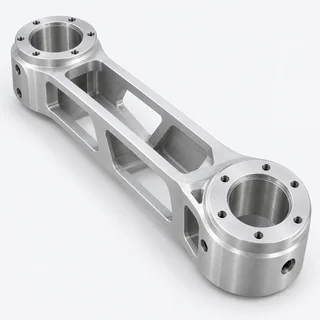
Wall thickness and section shape establish much of the part’s stiffness and mass.
Sources & technical scope
Illustrative images of generic materials and components.
This step
Related references
Wall thickness and section shape establish much of the part’s stiffness and mass.
Material input to Section & geometry: Alloy selection.
Assembly input to Seats & mounting faces: Section & geometry.
This step
Related references
Hydro: alloy choice and material strengthNASA: composite joint designNASA: thermal stress at metal–composite jointsigus: specifying cables for robot motionTE Connectivity: robot connector selectionKollmorgen: frameless motor housings and thermal integrationSKF: aluminium housings and bearing fits (pp. 42, 70)Hydro · aluminium engineering and prototyping
Section & geometry
Wall thickness and section shape establish much of the part’s stiffness and mass.
Local interfaces can dictate dimensions before bulk strength does.
Inputs & supporting parts
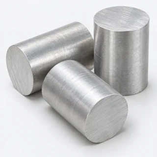
Material strength and processing behaviour influence structural design.
Where this fits
Bearing seats and joint interfaces locate the motion components.
Examples from industry 1
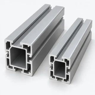 Generic
Hydro offers aluminium application development, engineering analysis and prototyping. These services sit between material selection and a finished structural part.
Sources & technical scope
Illustrative images of generic materials and components.
This step
Related references
Hydro: alloy choice and material strengthNASA: composite joint designNASA: thermal stress at metal–composite jointsigus: specifying cables for robot motionTE Connectivity: robot connector selectionKollmorgen: frameless motor housings and thermal integrationSKF: aluminium housings and bearing fits (pp. 42, 70)Hydro · aluminium engineering and prototyping
Bearing seats and joint interfaces locate the motion components.
Assembly input to Seats & mounting faces: Section & geometry.
Production step for Seats & mounting faces: Machined seats, holes & joints.
Used in Frame or housing: Seats & mounting faces.
This step
NASA: composite joint designNASA: thermal stress at metal–composite jointsigus: specifying cables for robot motionTE Connectivity: robot connector selectionKollmorgen: frameless motor housings and thermal integrationSKF: aluminium housings and bearing fits (pp. 42, 70)Hydro: alloy choice and material strength
Seats & mounting faces
Bearings →Bearing seats and joint interfaces locate the motion components.
Dimensional control at these faces affects the assembled joint.
Inputs & supporting parts
Wall thickness and section shape establish much of the part’s stiffness and mass.
Turning, drilling, milling and threading add the interfaces that extrusion cannot finish.
Where this fits
The structure carries load and locates internal components.
Sources & technical scope
Illustrative images of generic materials and components.
This step
Link to this detailNASA: composite joint designNASA: thermal stress at metal–composite jointsigus: specifying cables for robot motionTE Connectivity: robot connector selectionKollmorgen: frameless motor housings and thermal integrationSKF: aluminium housings and bearing fits (pp. 42, 70)Hydro: alloy choice and material strength
The structure carries load and locates internal components.
Used in Frame or housing: Seats & mounting faces.
Supporting dependency for Frame or housing: Thermal contact.
Production step for Frame or housing: Machined seats, holes & joints.
Sequence: Casting dimensional inspection → Frame or housing.
Sequence: Anodic pore sealing → Frame or housing.
Used in Robot structure: Frame or housing.
This step
NASA: composite joint designNASA: thermal stress at metal–composite jointsigus: specifying cables for robot motionTE Connectivity: robot connector selectionKollmorgen: frameless motor housings and thermal integrationSKF: aluminium housings and bearing fits (pp. 42, 70)Hydro: alloy choice and material strength
Frame or housing
The structure carries load and locates internal components.
A joint housing may also conduct motor heat.
Inputs & supporting parts
Bearing seats and joint interfaces locate the motion components.
Housing contact and exposed area affect heat rejection from an integrated motor.
Turning, drilling, milling and threading add the interfaces that extrusion cannot finish.
Dimensional inspection checks the finished interfaces against the drawing.
Sealing closes pores in the oxide layer.
Where this fits
Connections, load paths and service access complete the structural assembly.
Sources & technical scope
Illustrative images of generic materials and components.
This step
NASA: composite joint designNASA: thermal stress at metal–composite jointsigus: specifying cables for robot motionTE Connectivity: robot connector selectionKollmorgen: frameless motor housings and thermal integrationSKF: aluminium housings and bearing fits (pp. 42, 70)Hydro: alloy choice and material strength
Related references
Connections, load paths and service access complete the structural assembly.
Used in Robot structure: Frame or housing.
Supporting dependency for Robot structure: Composite joints.
Supporting dependency for Robot structure: Cables & service access.
This step
Related references
NASA: composite joint designNASA: thermal stress at metal–composite jointsigus: specifying cables for robot motionTE Connectivity: robot connector selectionKollmorgen: frameless motor housings and thermal integrationSKF: aluminium housings and bearing fits (pp. 42, 70)Hydro: alloy choice and material strength
Robot structure
Connections, load paths and service access complete the structural assembly.
Outer covers need not carry the joint loads.
Inputs & supporting parts
The structure carries load and locates internal components.
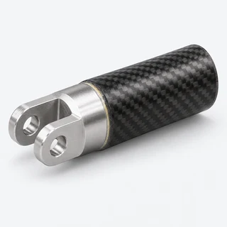
Composite links need connections designed for their load paths and material behaviour.
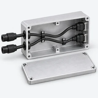
Moving harnesses need room to bend and twist, with accessible connectors.
Sources & technical scope
Illustrative images of generic materials and components.
This step
Related references
NASA: composite joint designNASA: thermal stress at metal–composite jointsigus: specifying cables for robot motionTE Connectivity: robot connector selectionKollmorgen: frameless motor housings and thermal integrationSKF: aluminium housings and bearing fits (pp. 42, 70)Hydro: alloy choice and material strength
Composite links need connections designed for their load paths and material behaviour.
Design alternative for Composite joints: Fibre–resin prepreg.
Supporting dependency for Composite joints: Cured-laminate inspection.
Supporting dependency for Robot structure: Composite joints.
Composite joints
Composite links need connections designed for their load paths and material behaviour.
Metal–composite interfaces also face differential thermal expansion.
Inputs & supporting parts
Prepreg combines reinforcement with a resin system before composite-part manufacture.
Visual inspection finds surface porosity; ultrasound or thermography can reveal internal porosity and inclusions.
Where this fits
Connections, load paths and service access complete the structural assembly.
Sources & technical scope
Illustrative images of generic materials and components.
Related references
Housing contact and exposed area affect heat rejection from an integrated motor.
Supporting dependency for Frame or housing: Thermal contact.
This step
NASA: composite joint designNASA: thermal stress at metal–composite jointsigus: specifying cables for robot motionTE Connectivity: robot connector selectionKollmorgen: frameless motor housings and thermal integrationSKF: aluminium housings and bearing fits (pp. 42, 70)Hydro: alloy choice and material strength
Thermal contact
Frameless motors →Housing contact and exposed area affect heat rejection from an integrated motor.
An outer cover can change the heat path.
Where this fits
The structure carries load and locates internal components.
Sources & technical scope
Illustrative images of generic materials and components.
This step
Link to this detailNASA: composite joint designNASA: thermal stress at metal–composite jointsigus: specifying cables for robot motionTE Connectivity: robot connector selectionKollmorgen: frameless motor housings and thermal integrationSKF: aluminium housings and bearing fits (pp. 42, 70)Hydro: alloy choice and material strength
Moving harnesses need room to bend and twist, with accessible connectors. Cable construction, routing and free length determine the loads at each joint.
Supporting dependency for Robot structure: Cables & service access.
This step
NASA: composite joint designNASA: thermal stress at metal–composite jointsigus: specifying cables for robot motionTE Connectivity: robot connector selectionKollmorgen: frameless motor housings and thermal integrationSKF: aluminium housings and bearing fits (pp. 42, 70)Hydro: alloy choice and material strength
Related references
Cables & service access
Moving harnesses need room to bend and twist, with accessible connectors. Cable construction, routing and free length determine the loads at each joint.
Bend-cycle and torsion tests measure different cable motions.
Where this fits
Connections, load paths and service access complete the structural assembly.
Sources & technical scope
Illustrative images of generic materials and components.
This step
NASA: composite joint designNASA: thermal stress at metal–composite jointsigus: specifying cables for robot motionTE Connectivity: robot connector selectionKollmorgen: frameless motor housings and thermal integrationSKF: aluminium housings and bearing fits (pp. 42, 70)Hydro: alloy choice and material strength
Related references
Prepreg combines reinforcement with a resin system before composite-part manufacture.
Design alternative for Composite joints: Fibre–resin prepreg.
Material input to Prepreg layup: Fibre–resin prepreg.
Fibre–resin prepreg
Prepreg combines reinforcement with a resin system before composite-part manufacture.
Fibre layup, cure cycle and connection design determine finished-part performance.
Where this fits
Composite links need connections designed for their load paths and material behaviour.
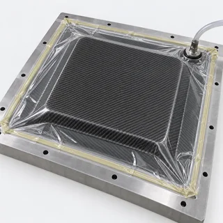
Reinforcement and resin prepreg are placed on tooling in the required ply arrangement.
Examples from industry 1
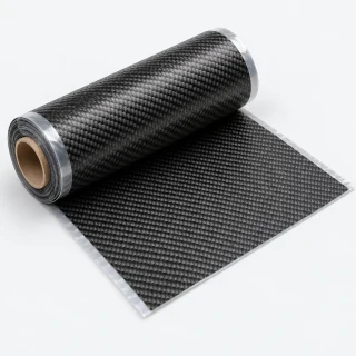 Generic
Toray CMA offers prepregs combining reinforcing fibres with epoxy or BMI resin systems, in formats such as unidirectional tape and woven fabrics.
Sources & technical scope
Illustrative images of generic materials and components.
Related references
Hydro offers aluminium application development, engineering analysis and prototyping. These services sit between material selection and a finished structural part.
Related references
Hydro · extrusion engineering
Manufacturer offeringHydro offers aluminium application development, engineering analysis and prototyping. These services sit between material selection and a finished structural part.
Part geometry, loads and production quantity determine the manufacturing route.
Where this fits
Wall thickness and section shape establish much of the part’s stiffness and mass.
Sources & technical scope
Illustrative images of generic materials and components.
Related references
Toray CMA offers prepregs combining reinforcing fibres with epoxy or BMI resin systems, in formats such as unidirectional tape and woven fabrics.
Toray Composite Materials America · prepreg
Manufacturer offeringToray CMA offers prepregs combining reinforcing fibres with epoxy or BMI resin systems, in formats such as unidirectional tape and woven fabrics.
Fibre orientation, resin cure and joint design determine how loads pass through the finished part.
Where this fits
Prepreg combines reinforcement with a resin system before composite-part manufacture.
Sources & technical scope
Illustrative images of generic materials and components.
Link to this detailExtrusion starts with a heated aluminium-alloy billet.
Production step for Aluminium billet: Alloying & billet casting.
Material input to Profile extrusion: Aluminium billet.
Aluminium billet
Extrusion starts with a heated aluminium-alloy billet.
Alloy and temper remain separate from the profile’s final geometry.
Inputs & supporting parts
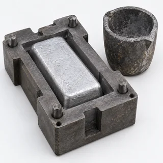
Liquid aluminium is alloyed and cast into stock for downstream shaping.
Where this fits
Pressure forces the heated billet through the die to form a profile.
Sources & technical scope
Illustrative images of generic materials and components.
Related references
The extrusion die shapes the heated billet into a profile. Tooling also forms the internal cavity of a hollow section.
Production step for Profile die & tooling: Tool-steel die manufacture.
Design alternative for Profile die & tooling: Hollow-profile die.
Checks on Profile die & tooling: Trial pressing & die correction.
Production equipment for Profile extrusion: Profile die & tooling.
Related references
Profile die & tooling
A shaped steel die defines the extruded profile; hollow profiles need tooling that also forms the internal cavity.
Inputs & supporting parts
CAD and flow simulation define the die.
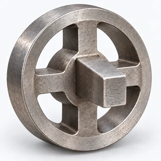
A mandrel forms the hollow section.
Where this fits
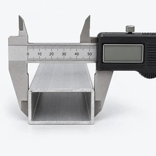
Measurements of the first profile’s dimensions and surface finish guide die corrections before series production.
Pressure forces the heated billet through the die to form a profile.
Sources & technical scope
Illustrative images of generic materials and components.
Related references
Pressure forces the heated billet through the die to form a profile.
Material input to Profile extrusion: Aluminium billet.
Production equipment for Profile extrusion: Profile die & tooling.
Sequence: Profile extrusion → Quenching & straightening.
Profile extrusion
Pressure forces the heated billet through the die to form a profile.
Inputs & supporting parts
Extrusion starts with a heated aluminium-alloy billet.
A shaped steel die defines the extruded profile; hollow profiles need tooling that also forms the internal cavity.
Where this fits
The extruded profile is cooled, stretched straight and cut to length.
Sources & technical scope
Illustrative images of generic materials and components.
Related references
First-article checks and die correction establish the profile’s dimensions and surface quality.
Checks on Ageing & stock preparation: Profile validation.
Sequence: Trial pressing & die correction → Profile validation.
Sequence: Profile validation → Machined seats, holes & joints.
Profile validation
First-article checks and die correction establish the profile’s dimensions and surface quality.
Finished bearing seats and mounting faces still need their own tolerances.
Inputs & supporting parts
Natural or controlled oven ageing develops the alloy’s required condition.
Measurements of the first profile’s dimensions and surface finish guide die corrections before series production.
Where this fits
Turning, drilling, milling and threading add the interfaces that extrusion cannot finish.
Sources & technical scope
Illustrative images of generic materials and components.
Related references
Reinforcement and resin prepreg are placed on tooling in the required ply arrangement.
Material input to Prepreg layup: Fibre–resin prepreg.
Production equipment for Prepreg layup: Mould & vacuum bag.
Sequence: Prepreg layup → Vacuum consolidation.
Related references
Prepreg layup
Reinforcement and resin prepreg are placed on tooling in the required ply arrangement.
Inputs & supporting parts
Prepreg combines reinforcement with a resin system before composite-part manufacture.
The mould defines the part surface.
Where this fits
Bagging removes trapped air and consolidates the layup before and during the specified cure process.
Sources & technical scope
Illustrative images of generic materials and components.
Related references
Bagging removes trapped air and consolidates the layup before and during the specified cure process.
Sequence: Prepreg layup → Vacuum consolidation.
Material input to Vacuum consolidation: Release film & breather fabric.
Sequence: Vacuum consolidation → Controlled cure & cooling.
Vacuum consolidation
Bagging removes trapped air and consolidates the layup before and during the specified cure process.
Vacuum integrity and consumables are manufacturing dependencies.
Inputs & supporting parts
Reinforcement and resin prepreg are placed on tooling in the required ply arrangement.
Release layers separate the cured part from tooling and bag materials.
Where this fits
Time, temperature and pressure follow the prepreg’s specified cycle, with controlled cooling.
Sources & technical scope
Illustrative images of generic materials and components.
Link to this detailThe resin system sets the cure temperature, time and pressure. Controlled curing and cooling produce the finished laminate.
Sequence: Vacuum consolidation → Controlled cure & cooling.
Checks on Controlled cure & cooling: Cured-laminate inspection.
Controlled cure & cooling
Time, temperature and pressure follow the prepreg’s specified cycle, with controlled cooling.
The resin system determines the oven or autoclave cure cycle.
Inputs & supporting parts
Bagging removes trapped air and consolidates the layup before and during the specified cure process.
Where this fits
Visual inspection finds surface porosity; ultrasound or thermography can reveal internal porosity and inclusions.
Sources & technical scope
Illustrative images of generic materials and components.
Link to this detailVisual inspection finds surface porosity; ultrasound or thermography can reveal internal porosity and inclusions.
Checks on Controlled cure & cooling: Cured-laminate inspection.
Supporting dependency for Composite joints: Cured-laminate inspection.
Cured-laminate inspection
Visual inspection finds surface porosity; ultrasound or thermography can reveal internal porosity and inclusions.
Inputs & supporting parts
Time, temperature and pressure follow the prepreg’s specified cycle, with controlled cooling.
Where this fits
Composite links need connections designed for their load paths and material behaviour.
Sources & technical scope
Illustrative images of generic materials and components.
Related references
CAD and flow simulation define the die. Machined tool steel receives heat treatment and, where required, a wear-resistant surface treatment.
Material input to Tool-steel die manufacture: Die steel.
Production step for Profile die & tooling: Tool-steel die manufacture.
Tool-steel die manufacture
CAD and flow simulation define the die. Machined tool steel receives heat treatment and, where required, a wear-resistant surface treatment.
Equipment for this step →Inputs & supporting parts
Tool steel is the upstream stock for extrusion dies.
Where this fits
A shaped steel die defines the extruded profile; hollow profiles need tooling that also forms the internal cavity.
Sources & technical scope
Illustrative images of generic materials and components.
Link to this detailA mandrel forms the hollow section. In bridge tooling, aluminium flow divides around the supporting bridges and rejoins inside the die.
Design alternative for Profile die & tooling: Hollow-profile die.
Hollow-profile die
A mandrel forms the hollow section. In bridge tooling, aluminium flow divides around the supporting bridges and rejoins inside the die.
Where this fits
A shaped steel die defines the extruded profile; hollow profiles need tooling that also forms the internal cavity.
Sources & technical scope
Illustrative images of generic materials and components.
Link to this detailMeasurements of the first profile’s dimensions and surface finish guide die corrections before series production.
Checks on Profile die & tooling: Trial pressing & die correction.
Sequence: Trial pressing & die correction → Profile validation.
Trial pressing & die correction
Measurements of the first profile’s dimensions and surface finish guide die corrections before series production.
Inputs & supporting parts
A shaped steel die defines the extruded profile; hollow profiles need tooling that also forms the internal cavity.
Where this fits
First-article checks and die correction establish the profile’s dimensions and surface quality.
Sources & technical scope
Illustrative images of generic materials and components.
Link to this detailRelease layers separate the cured part from tooling and bag materials. Breather fabric provides an air path; optional bleeder fabric absorbs excess resin.
Material input to Vacuum consolidation: Release film & breather fabric.
Release film & breather fabric
Release layers separate the cured part from tooling and bag materials. Breather fabric provides an air path; optional bleeder fabric absorbs excess resin.
Where this fits
Bagging removes trapped air and consolidates the layup before and during the specified cure process.
Sources & technical scope
Illustrative images of generic materials and components.
Link to this detailThe mould defines the part surface. Sealant tape and a leak-tight bag allow vacuum consolidation during the resin’s specified cure cycle.
Production equipment for Prepreg layup: Mould & vacuum bag.
Mould & vacuum bag
The mould defines the part surface. Sealant tape and a leak-tight bag allow vacuum consolidation during the resin’s specified cure cycle.
Where this fits
Reinforcement and resin prepreg are placed on tooling in the required ply arrangement.
Sources & technical scope
Illustrative images of generic materials and components.
Link to this detailThe extruded profile is cooled, stretched straight and cut to length. Cooling and straightening precede the specified ageing treatment.
Sequence: Profile extrusion → Quenching & straightening.
Sequence: Quenching & straightening → Ageing & stock preparation.
Related references
Quenching & straightening
The extruded profile is cooled, stretched straight and cut to length. Cooling and straightening precede the specified ageing treatment.
Inputs & supporting parts
Pressure forces the heated billet through the die to form a profile.
Where this fits
Natural or controlled oven ageing develops the alloy’s required condition.
Sources & technical scope
Illustrative images of generic materials and components.
Related references
Natural or controlled oven ageing develops the alloy’s required condition. The prepared profile can then receive machining and surface finishing.
Sequence: Quenching & straightening → Ageing & stock preparation.
Checks on Ageing & stock preparation: Profile validation.
Related references
Ageing & stock preparation
Natural or controlled oven ageing develops the alloy’s required condition. The prepared profile can then receive machining and surface finishing.
Inputs & supporting parts
The extruded profile is cooled, stretched straight and cut to length.
Where this fits
First-article checks and die correction establish the profile’s dimensions and surface quality.
Sources & technical scope
Illustrative images of generic materials and components.
Related references
Turning, drilling, milling and threading add the interfaces that extrusion cannot finish. Deburring removes machining edges before joining or fitting inserts.
Sequence: Profile validation → Machined seats, holes & joints.
Production step for Frame or housing: Machined seats, holes & joints.
Production step for Seats & mounting faces: Machined seats, holes & joints.
Sequence: Machined seats, holes & joints → Surface deburring & preparation.
Related references
Hydro · extrusion dies and first-article validationNASA: composite joint designNASA: thermal stress at metal–composite jointsigus: specifying cables for robot motionTE Connectivity: robot connector selectionKollmorgen: frameless motor housings and thermal integrationSKF: aluminium housings and bearing fits (pp. 42, 70)Hydro: alloy choice and material strengthHydro · mechanical preparation and surface properties
Machined seats, holes & joints
Turning, drilling, milling and threading add the interfaces that extrusion cannot finish. Deburring removes machining edges before joining or fitting inserts.
Equipment for this step →Inputs & supporting parts
First-article checks and die correction establish the profile’s dimensions and surface quality.
Where this fits
The structure carries load and locates internal components.
Bearing seats and joint interfaces locate the motion components.
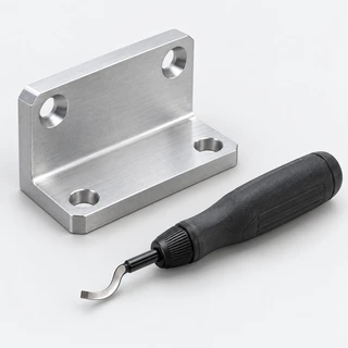
Mechanical finishing removes burrs and machining marks.
Sources & technical scope
Illustrative images of generic materials and components.
Related references
Hydro · extrusion dies and first-article validationNASA: composite joint designNASA: thermal stress at metal–composite jointsigus: specifying cables for robot motionTE Connectivity: robot connector selectionKollmorgen: frameless motor housings and thermal integrationSKF: aluminium housings and bearing fits (pp. 42, 70)Hydro: alloy choice and material strengthHydro · mechanical preparation and surface properties
Bauxite supplies the aluminium-bearing feed for primary alumina production.
Material input to Alumina refining: Bauxite ore.
Bauxite ore
Bauxite supplies the aluminium-bearing feed for primary alumina production.
Where this fits
The Bayer process extracts aluminium oxide from bauxite.
Sources & technical scope
Illustrative images of generic materials and components.
Link to this detailThe Bayer process extracts aluminium oxide from bauxite.
Material input to Alumina refining: Bauxite ore.
Sequence: Alumina refining → Aluminium electrolysis.
Alumina refining
The Bayer process extracts aluminium oxide from bauxite.
Alumina refining and aluminium smelting are distinct industrial steps.
Inputs & supporting parts
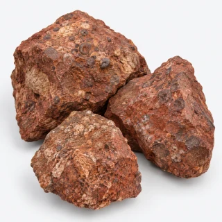
Bauxite supplies the aluminium-bearing feed for primary alumina production.
Where this fits
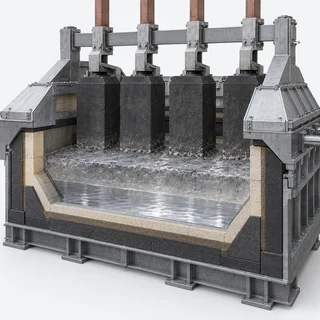
Electricity separates aluminium from oxygen in alumina to produce primary metal.
Sources & technical scope
Illustrative images of generic materials and components.
Link to this detailElectricity separates aluminium from oxygen in alumina to produce primary metal.
Sequence: Alumina refining → Aluminium electrolysis.
Sequence: Aluminium electrolysis → Alloying & billet casting.
Aluminium electrolysis
Electricity separates aluminium from oxygen in alumina to produce primary metal.
Inputs & supporting parts
The Bayer process extracts aluminium oxide from bauxite.
Where this fits
Liquid aluminium is alloyed and cast into stock for downstream shaping.
Sources & technical scope
Illustrative images of generic materials and components.
Link to this detailLiquid aluminium is alloyed and cast into stock for downstream shaping.
Sequence: Aluminium electrolysis → Alloying & billet casting.
Material input to Alloying & billet casting: Sorted aluminium scrap.
Production step for Aluminium billet: Alloying & billet casting.
Alloying & billet casting
Liquid aluminium is alloyed and cast into stock for downstream shaping.
Inputs & supporting parts
Electricity separates aluminium from oxygen in alumina to produce primary metal.
Sorted scrap can be remelted into new aluminium products.
Where this fits
Extrusion starts with a heated aluminium-alloy billet.
Sources & technical scope
Illustrative images of generic materials and components.
Related references
Sorted scrap can be remelted into new aluminium products.
Material input to Alloying & billet casting: Sorted aluminium scrap.
Sorted aluminium scrap
Sorted scrap can be remelted into new aluminium products.
Scrap composition must suit the required alloy; recycled feed is an alternative to an all-primary route.
Where this fits
Liquid aluminium is alloyed and cast into stock for downstream shaping.
Sources & technical scope
Illustrative images of generic materials and components.
Link to this detailAluminium casting alloy is melted in an external furnace before cold-chamber injection. Alloy choice and the part geometry determine the casting conditions.
Sequence: Casting alloy feed → Pressure casting.
Casting alloy feed
Aluminium casting alloy is melted in an external furnace before cold-chamber injection. Alloy choice and the part geometry determine the casting conditions.
Sources & technical scope
Illustrative images of generic materials and components.
Link to this detailThe die forms walls, ribs and mounting bosses. Gates feed the cavity; cooling and wall transitions influence shrinkage and porosity.
Production equipment for Pressure casting: Casting die & cooling.
Related references
Casting die & cooling
The die forms walls, ribs and mounting bosses. Gates feed the cavity; cooling and wall transitions influence shrinkage and porosity.
Sources & technical scope
Illustrative images of generic materials and components.
Related references
Molten alloy fills the die under pressure and solidifies into a near-net-shape housing. Cold-chamber casting is a common aluminium route.
Sequence: Casting alloy feed → Pressure casting.
Production equipment for Pressure casting: Casting die & cooling.
Sequence: Pressure casting → Ejection & trimming.
Related references
Pressure casting
Molten alloy fills the die under pressure and solidifies into a near-net-shape housing. Cold-chamber casting is a common aluminium route.
Inputs & supporting parts
Aluminium casting alloy is melted in an external furnace before cold-chamber injection.
The die forms walls, ribs and mounting bosses.
Where this fits
The casting leaves the opened die; gates, runners and flash are removed before finishing.
Sources & technical scope
Illustrative images of generic materials and components.
Related references
The casting leaves the opened die; gates, runners and flash are removed before finishing. Draft on the walls helps the part release.
Sequence: Pressure casting → Ejection & trimming.
Sequence: Ejection & trimming → Cast-part machining & finish.
Ejection & trimming
The casting leaves the opened die; gates, runners and flash are removed before finishing. Draft on the walls helps the part release.
Inputs & supporting parts
Molten alloy fills the die under pressure and solidifies into a near-net-shape housing.
Where this fits
Secondary machining produces precise seats and holes.
Sources & technical scope
Illustrative images of generic materials and components.
Related references
Secondary machining produces precise seats and holes. Cleaning and surface finishing prepare the part for its operating environment.
Sequence: Ejection & trimming → Cast-part machining & finish.
Sequence: Moulded magnesium part → Cast-part machining & finish.
Sequence: Cast-part machining & finish → Casting dimensional inspection.
Cast-part machining & finish
Secondary machining produces precise seats and holes. Cleaning and surface finishing prepare the part for its operating environment.
Inputs & supporting parts
The casting leaves the opened die; gates, runners and flash are removed before finishing.
The moulded workpiece proceeds to the specified interface machining and surface treatment.
Where this fits
Dimensional inspection checks the finished interfaces against the drawing.
Sources & technical scope
Illustrative images of generic materials and components.
Related references
Dimensional inspection checks the finished interfaces against the drawing. The inspection plan also addresses casting defects and cleanliness.
Sequence: Cast-part machining & finish → Casting dimensional inspection.
Sequence: Casting dimensional inspection → Frame or housing.
Related references
NASA: composite joint designNASA: thermal stress at metal–composite jointsigus: specifying cables for robot motionTE Connectivity: robot connector selectionKollmorgen: frameless motor housings and thermal integrationSKF: aluminium housings and bearing fits (pp. 42, 70)Hydro: alloy choice and material strength
Casting dimensional inspection
Dimensional inspection checks the finished interfaces against the drawing. The inspection plan also addresses casting defects and cleanliness.
Inputs & supporting parts
Secondary machining produces precise seats and holes.
Where this fits
The structure carries load and locates internal components.
Sources & technical scope
Illustrative images of generic materials and components.
Related references
NASA: composite joint designNASA: thermal stress at metal–composite jointsigus: specifying cables for robot motionTE Connectivity: robot connector selectionKollmorgen: frameless motor housings and thermal integrationSKF: aluminium housings and bearing fits (pp. 42, 70)Hydro: alloy choice and material strength
Cut magnesium-alloy chips feed the injection-moulding machine. This route heats the feed inside a cylinder rather than an external melting furnace.
Sequence: Magnesium alloy chips → Semi-solid magnesium preparation.
Magnesium alloy chips
Cut magnesium-alloy chips feed the injection-moulding machine. This route heats the feed inside a cylinder rather than an external melting furnace.
Sources & technical scope
Illustrative images of generic materials and components.
Link to this detailHeating and screw shearing create a semi-molten alloy with the flow behaviour required for injection.
Sequence: Magnesium alloy chips → Semi-solid magnesium preparation.
Sequence: Semi-solid magnesium preparation → Magnesium injection moulding.
Semi-solid magnesium preparation
Heating and screw shearing create a semi-molten alloy with the flow behaviour required for injection.
Inputs & supporting parts
Cut magnesium-alloy chips feed the injection-moulding machine.
Where this fits
The semi-solid alloy is injected from the cylinder into a mould without exposure to the atmosphere during transfer.
Sources & technical scope
Illustrative images of generic materials and components.
Link to this detailThe semi-solid alloy is injected from the cylinder into a mould without exposure to the atmosphere during transfer. The mould forms thin walls and detailed features.
Sequence: Semi-solid magnesium preparation → Magnesium injection moulding.
Sequence: Magnesium injection moulding → Moulded magnesium part.
Magnesium injection moulding
The semi-solid alloy is injected from the cylinder into a mould without exposure to the atmosphere during transfer. The mould forms thin walls and detailed features.
Inputs & supporting parts
Heating and screw shearing create a semi-molten alloy with the flow behaviour required for injection.
Where this fits
The moulded workpiece proceeds to the specified interface machining and surface treatment.
Sources & technical scope
Illustrative images of generic materials and components.
Link to this detailThe moulded workpiece proceeds to the specified interface machining and surface treatment. Housing geometry and interfaces determine its role in the assembly.
Sequence: Magnesium injection moulding → Moulded magnesium part.
Sequence: Moulded magnesium part → Cast-part machining & finish.
Related references
Moulded magnesium part
The moulded workpiece proceeds to the specified interface machining and surface treatment. Housing geometry and interfaces determine its role in the assembly.
Inputs & supporting parts
The semi-solid alloy is injected from the cylinder into a mould without exposure to the atmosphere during transfer.
Where this fits
Secondary machining produces precise seats and holes.
Sources & technical scope
Illustrative images of generic materials and components.
Related references
Polymer pellets feed a heated barrel. Resin grade determines processing temperature, shrinkage and the finished part’s properties.
Sequence: Thermoplastic pellets → Polymer melting & injection.
Thermoplastic pellets
Polymer pellets feed a heated barrel. Resin grade determines processing temperature, shrinkage and the finished part’s properties.
Sources & technical scope
Illustrative images of generic materials and components.
Link to this detailThe mould cavity defines the cover or guide. Runners and gates carry molten polymer into the cavity.
Production equipment for Polymer melting & injection: Plastic mould tooling.
Plastic mould tooling
The mould cavity defines the cover or guide. Runners and gates carry molten polymer into the cavity.
Sources & technical scope
Illustrative images of generic materials and components.
Link to this detailThe barrel melts the pellets and injects polymer through runners and gates into the mould.
Sequence: Thermoplastic pellets → Polymer melting & injection.
Production equipment for Polymer melting & injection: Plastic mould tooling.
Sequence: Polymer melting & injection → Cooling & part ejection.
Polymer melting & injection
The barrel melts the pellets and injects polymer through runners and gates into the mould.
Inputs & supporting parts
Polymer pellets feed a heated barrel.
The mould cavity defines the cover or guide.
Where this fits
The polymer solidifies in the mould, which opens to release the part.
Sources & technical scope
Illustrative images of generic materials and components.
Link to this detailThe polymer solidifies in the mould, which opens to release the part. Cooling and shrinkage affect the final dimensions.
Sequence: Polymer melting & injection → Cooling & part ejection.
Sequence: Cooling & part ejection → Moulded cover or guide.
Cooling & part ejection
The polymer solidifies in the mould, which opens to release the part. Cooling and shrinkage affect the final dimensions.
Sources & technical scope
Illustrative images of generic materials and components.
Link to this detailMoulding produces shaped covers and cable guides. The selected material, wall geometry and mounting features establish their mechanical role.
Sequence: Cooling & part ejection → Moulded cover or guide.
Moulded cover or guide
Moulding produces shaped covers and cable guides. The selected material, wall geometry and mounting features establish their mechanical role.
Sources & technical scope
Illustrative images of generic materials and components.
Link to this detailMechanical finishing removes burrs and machining marks. Polishing, blasting or tumbling establishes the surface texture before chemical treatment.
Sequence: Machined seats, holes & joints → Surface deburring & preparation.
Sequence: Surface deburring & preparation → Cleaning, etching & desmutting.
Surface deburring & preparation
Mechanical finishing removes burrs and machining marks. Polishing, blasting or tumbling establishes the surface texture before chemical treatment.
Inputs & supporting parts
Turning, drilling, milling and threading add the interfaces that extrusion cannot finish.
Where this fits
Degreasing removes contamination; etching treats the aluminium surface and desmutting removes alloy residues.
Sources & technical scope
Illustrative images of generic materials and components.
Link to this detailDegreasing removes contamination; etching treats the aluminium surface and desmutting removes alloy residues. Rinses separate the treatment baths.
Sequence: Surface deburring & preparation → Cleaning, etching & desmutting.
Sequence: Cleaning, etching & desmutting → Anodic oxide formation.
This step
Related references
Cleaning, etching & desmutting
Degreasing removes contamination; etching treats the aluminium surface and desmutting removes alloy residues. Rinses separate the treatment baths.
Inputs & supporting parts
Mechanical finishing removes burrs and machining marks.
Where this fits
Electrical current through an acid bath converts the aluminium surface to oxide.
Sources & technical scope
Illustrative images of generic materials and components.
This step
Related references
Electrical current through an acid bath converts the aluminium surface to oxide. Alloy and process conditions determine the finish.
Sequence: Cleaning, etching & desmutting → Anodic oxide formation.
Sequence: Anodic oxide formation → Anodic pore sealing.
This step
Anodic oxide formation
Electrical current through an acid bath converts the aluminium surface to oxide. Alloy and process conditions determine the finish.
Inputs & supporting parts
Degreasing removes contamination; etching treats the aluminium surface and desmutting removes alloy residues.
Where this fits
Sealing closes pores in the oxide layer.
Sources & technical scope
Illustrative images of generic materials and components.
This step
Link to this detailSealing closes pores in the oxide layer. Optional colouring takes place beforehand. The treatment improves corrosion resistance and changes surface properties.
Sequence: Anodic oxide formation → Anodic pore sealing.
Sequence: Anodic pore sealing → Frame or housing.
This step
Related references
NASA: composite joint designNASA: thermal stress at metal–composite jointsigus: specifying cables for robot motionTE Connectivity: robot connector selectionKollmorgen: frameless motor housings and thermal integrationSKF: aluminium housings and bearing fits (pp. 42, 70)Hydro: alloy choice and material strength
Anodic pore sealing
Sealing closes pores in the oxide layer. Optional colouring takes place beforehand. The treatment improves corrosion resistance and changes surface properties.
Inputs & supporting parts
Electrical current through an acid bath converts the aluminium surface to oxide.
Where this fits
The structure carries load and locates internal components.
Sources & technical scope
Illustrative images of generic materials and components.
This step
Related references
NASA: composite joint designNASA: thermal stress at metal–composite jointsigus: specifying cables for robot motionTE Connectivity: robot connector selectionKollmorgen: frameless motor housings and thermal integrationSKF: aluminium housings and bearing fits (pp. 42, 70)Hydro: alloy choice and material strength
Tool steel is the upstream stock for extrusion dies. Machining, heat treatment and any wear-resistant surface treatment turn that stock into profile tooling.
Material input to Tool-steel die manufacture: Die steel.
Die steel
Tool steel is the upstream stock for extrusion dies. Machining, heat treatment and any wear-resistant surface treatment turn that stock into profile tooling.
Where this fits
CAD and flow simulation define the die.
Sources & technical scope
Illustrative images of generic materials and components.
Link to this detailProduction equipment
- DMG MORIFive-axis machining centres
Five-axis machining cuts housing interfaces, mounting faces and complex tooling. The same machine class produces structural parts and moulds from solid stock.
Precision machining →Sources
Actuator housings and robot structures · machined interfaces and tooling
DMG MORI · structural components, housings and die-and-mould machining
Market context
MEVIUS2 · fabrication and hardware cost
US$6,150Metal parts · research build
US$12,905Total hardware · including metal parts
One research build’s procurement budget, including motors and sensors.
Lens Technology
10,000Rover X1 robots · assembly order
Complete-machine assembly order for Rover X1.
Xingyuan

Xingyuan Zhuomei reported RMB3.406 million in robot lightweight-component revenue in H1 2026. The robot-parts programme spans customer qualification, samples and small-batch production, including collaborative-robot applications.
Unitree
Unitree assembles robots and core modules internally. It buys custom mechanical parts and outsources most PCB assembly, injection moulding and some machining.
Companies
Browse components →Lens TechnologySupply connection · DobotUnitreein-house assembly and outside processingXingyuan ZhuomeiMagnesium robot frames, joint parts and housingsZhejiang Tiandiao PrecisionSupply connection · Unitree
Explore documented supply relationships →